
Overview
!!!!!!!!!!!!!!!!!!!!!!!!!!!!!!!!!!!!!!!!!!!!!!!!!!!!!!!!!!!!!!!!!!!!!!!!!!
You’ve landed on an older page that we’re keeping around for reference a little longer. We strongly recommend you check out our latest installation page at https://awesome.tech/installing-the-mini-gerbil/
!!!!!!!!!!!!!!!!!!!!!!!!!!!!!!!!!!!!!!!!!!!!!!!!!!!!!!!!!!!!!!!!!!!!!!!!!!
You’ll be disconnecting connectors from your K40’s existing controller, and reconnecting them to the Mini Gerbil. It’s a great idea to read all the instructions below before starting. Basic familiarity with connectors/electronics is helpful, but the forum is a great place to ask questions if you’re unsure about anything. Typically takes 10-20 minutes.
First, be aware there are many K40 versions, with various combinations of:
- Control panel – Digital and Analogue versions (panel or potmeter knob)
- Connector lead – ribbon cable version (X axis motor plus the limit switches) and non-ribbon version – individually wired x/y axis and limit switches (more info is provided in the forum, see click to thread on k40 forum page)
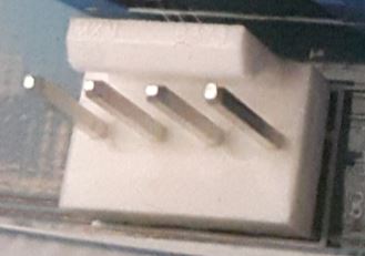
- Power supply type (PSU) – All screw Terminals, Micro plugs for LP(2pins),WP(2pins),PWM(3pins)
- Limit switches – mechanical limit switches (two leads: signal and ground), and electronic limit switches (signal, ground and 5 Volt power)
So don’t worry if your K40 appears different to the diagrams below, just work through carefully to select the closest match.
For initial setup, we very strongly recommend using the standard homing position (back, left hand side) of your K40. For more details and alternatives, see https://awesome.tech/limit-switches-and-homing/
Tools and materials:
- Small screw driver
- Small nose pliers
Steps
Let’s start with mounting your Mini Gerbil onto the supplied mounting board – see https://awesome.tech/new-mini-gerbil-mounting-solution/
STEP 1 Turn your K40 power off at the wall (powerpoint).
Orientation
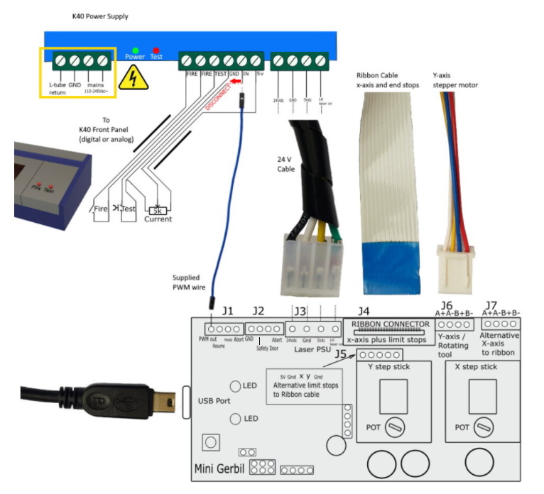
STEP 2 Open up the main panel on the right hand side of your K40. Inside you’ll see an electronics enclosure which is the K40 power supply:
The first two images show PSU type 1, the last image shows PSU type 2.

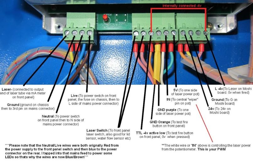

The leftmost connector in the above diagram is the mains voltage power connector – no need to touch this. The Gerbil installation only uses the leads associated with the centre and rightmost connectors.
STEP 3 Follow the the wires from the front of the power supply to the circuit board on the back of the K40’s front panel, and you’ve found the K40’s old controller, which looks like this:

(photo courtesy of: www.igorkromin.net)
STEP 4 Temporarily attach a label to any similarly coloured wires on the old controller so you can identify them later on if necessary
STEP 5 Take a close up photo of the wires coming into the old controller (like the above photo), ensuring you can clearly see which wires and labels attach to the various connectors.
STEP 6 Now take a look at the Mini Gerbil. It has headers with a lock mechanism to help you avoid plugging connectors in the wrong way around.
Disconnecting the old controller and connecting the Mini Gerbil
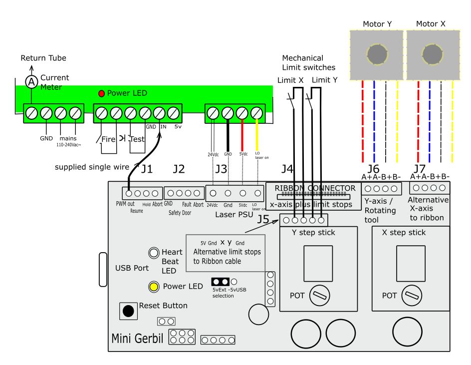
STEP 7 Unplug the small 4 wire Y axis motor connector from the old controller and plug into the Mini Gerbil headers, as shown in the picture below. The header lock mechanism prevents incorrect orientation. Note: if the machine does “home” away from zero during testing then you need to turn the connector 90 degrees or configure the firmware to revert the Y direction (via command $23=1 to reverse Y and keep X direction, $23=2 to reverse X and keep Y or reverse both axis via $23=0)


STEP 8 Unplug the large 4 wire Low Voltage connector from the old controller, and plug into the large header on the Mini Gerbil labelled J3 ‘Lo/5V/Gnd/24V’. The header lock mechanism prevents incorrect orientation.

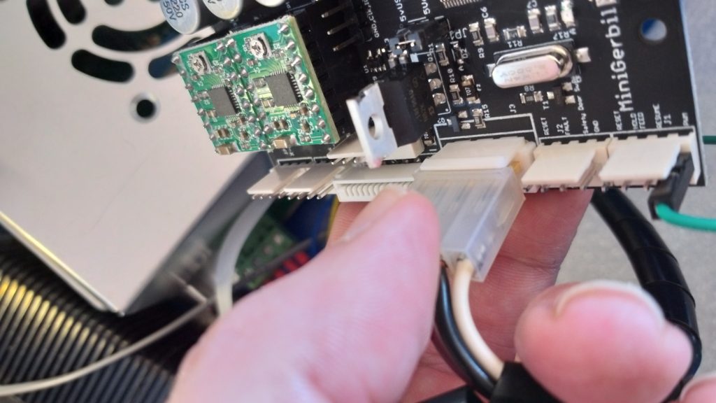

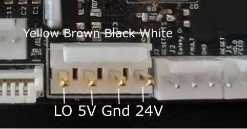
The photo above shows labels on the Mini Gerbil to aid orientation of the large low voltage power connector. (In some older versions of the K40, the connector has 6 positions with 4 wires. You can extract carefully the metal connector inserts and re-seat them in the right positions/sequence in the 6 pin socket connector and slide the 6 pin connector over the 4 male pins. Alternatively you can buy a standard 4 pin (MTA-156 – 4 Position 3.96 mm pitch) PC connector and use this to connect the Gerbil controller to the Laser power supply. See Digikey MTA connectors)
For K40 owners with a ribbon cable see step 9a. For K40 owners without a ribbon cable, see step 9b.
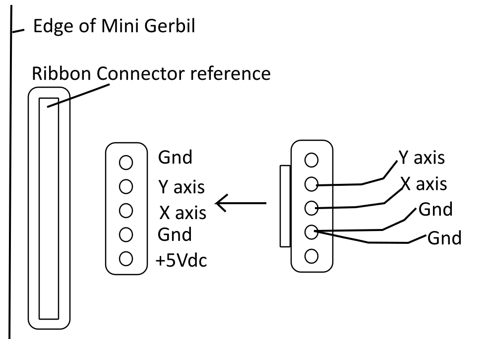
STEP 9a Unplug the ribbon cable from the old controller, and plug into the long thin slot in the Mini Gerbil. The metal lips of the ribbon cable must face the edge of the Gerbil, as shown below. If your version hasn’t got a ribbon cable then read : awesome.tech/k40-forum/?view=thread&id=31 . This post provides details and photographs.


STEP 9b: If your K40 has a plug for limit switches instead of a ribbon cable then you’ll need to connect it to the Mini Gerbil’s connector behind the ribbon connector. First, before disconnecting anything, review the wiring of the limit switch plug on the existing control board. The photo below shows the location – note carefully the labels on the NanoM2 board Y, X, GND (and 5V if applicable).

Now, look at the secondary connector behind the ribbon cable socket. Facing from the edge of the Mini Gerbil PCB V1.1A and looking towards the ribbon connector, the pins are GND, Y-Limit, X-Limit, GND and 5V. You only need the 5V supply if you have electronic (opto) limit switches. Note the ribbon and limit switch connectors are swapped around (pin header on the edge) on the Mini Gerbil 2.0 PCB for ease of connecting.
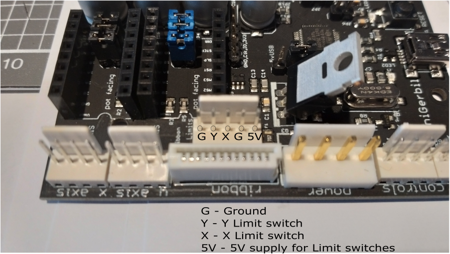
Install the limit switch plug from the old controller into the Mini Gerbil, carefully checking the wires are matched.
STEP 10: The strength of the laser beam is controlled by a ‘PWM’ wire. The existing PWM wire needs to be disconnected from the terminal strip and be replaced with the provided wire. To cover both K40 PSU options, we’ve provided one with Female/Male Dupont connectors as well as one with Female/Female connectors.
If you’re unsure which is your K40’s PWM wire, it comes from the middle of the current control potentiometer or digital control panel to the IN terminal shown on the power supply diagrams above.
Connect the supplied wire from the Mini Gerbil’s PWM output to the PWM input of the power supply as depicted above (labelled ‘IN’ terminal). The old current control wire can be left disconnected, and it’s recommended you wrap the end in electrical tape to avoid it potentially connecting with anything else.
STEP 11 Confirm your Y axis, Low Voltage and Ribbon connectors are now plugged into the Gerbil like this:
STEP 12 Disconnect the existing K40 USB lead from the old controller and plug into the Mini Gerbil. Plug the other end into your PC/MAC as usual.
Questions ? Please check our forum and refer to the instruction numbers above if posting a question
Software
Lightburn – strongly recommended
Let’s now setup your computer software for the Mini Gerbil. We strongly recommend Lightburn, see https://awesome.tech/download/lightburn-and-laserweb-instructions/
Inkscape
If you have a particular reason to use Inkscape, you’ll need to check:
Installing the Inkscape plugins
Various G-code senders
If you’re a G-code afficianado, you can use any G-code sender with Mini Gerbil. CNCjs and UGS are examples of compatible g-code senders but any others should work too. The default behavior of Mini Gerbil when powered up is to energise the motors in hold position (lock up). If your K40 uses a Door switch, you’ll need to clear the controller alarm via a command “$X”. The Inkscape plugins do that clear command by default when streaming the g-code files. After issuing a “$X” you can issue a g-code command like “G0 X1 Y1” t’o move the gantry or issue a “$H” to home the machine to its zero coordinates (Left Top corner same a stock K40). Command “S100” turns the laser on where the number stands for the power e.g. 100 equals 1mA. (Depending how you set the power range e.g. default $30=1000 equals 20mA so S100=2mA. You can experiment with this setting to get the best laser results). The following table shows G-code commands and their meanings
| M4 | laser on ($32=1 in laser mode, the laser only turns on when the gantry is in motion.) |
| G1 X1 Y1 S100 F800 | Goto coordinates X,Y (1,1) at a feed rate of 800mm/min with the tool (laser beam) powered at 1mA |
| M5 | switch it off |
G0 is a move without any tools enabled.
You can also home the machine via the $H command. If the machine does not home correctly then it can be that the axis motor connector needs to be swapped around (180 degrees, when homing away from zero or use the $23 settings to reverse the direction) or the end stops are not properly connected or engaging.
Limit code testing via G-code
You can test the limit switches via CNCJS. The status command “?” (yes, just type a question mark in the black box area called console in the G-code sender) provides status information back so you can see if they work when you push the gantry in the zero position. (Top left corner, set $1=100 so motors don’t lock while in rest. Later on revert back to 255 to keep the Gantry aligned and into the correct position). Some of the status line information might be hidden so expand the status message box. The limit switch information is at the end of the status line. If the limit switch is not triggered then there is no information. If triggered then you see something like <Idle|MPOS:0.000,0.000|Bf:0,255|Fs:0,0|Pn:X,Y>

Mirror Alignment via G-code
It’s handy to have short pulses of laser power when aligning mirrors. To do so with G-code, set Mini Gerbil in ‘CNC’ mode via ‘$32=0’, than you can switch-on the laser at rest via the G-code commands: ‘M3’/’M4’ and off via ‘M5’. Use the ‘Sxxx’ command to set the output power e.g ‘S200’ for 2mA output. Don’t forget to set ‘$32’ back to ‘1’ (Laser mode) for safety reasons (in laser mode the laser can only burn when the gantry is in motion). The P is for pause 1 sec (you can change the value ).
- $32=0
- M4 S200
- M5
- P1000
- $32=1
For all commands see Configuring Mini Gerbil wiki
https://github.com/paulusjacobus/grbl/wiki/Configuring-Gerbil-Grbl-v1.1f