
Overview
These instructions are for the Super Gerbil controller which is meant for CNC machines and Lasers with Z axis. For K40 lasers powered by Mini Gerbil see the Mini Gerbil instructions.
NOTE: BEFORE YOU START, READ THESE INSTRUCTIONS CAREFULLY. After you’ve read carefully, the instructions are designed to be followed from top to bottom.
Related pages are:
- Software setup
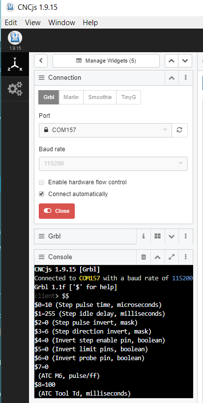
- Configuring the Super Gerbil
- Using the Super Gerbil
- Toy Truck example
The tools you need to install the Super Gerbil are:
- Small screw driver
- Set of small pliers (pcb mounting)
- Optional Wire stripper for motor and buttons
- Optional multi-meter to verify power
Hints and Tips for installation
- Take photos of previous installations for reference or follow up when you get stuck
- Don’t connect power or USB until you get to the relevant part of the instructions
- Don’t rush and take your time to check and review the installation
- Be safe and careful, don’t take risks
- Screw terminals: tight is just right. Don’t over tighten the screws
- Label and review your connections
- Layout all parts upfront in sequence so you don’t get frustrated by missing parts or components
- Plan upfront where you want to mount and install the controller so you know whether the cabling is long enough
- Add physical dimensions referred to in installations are in millimeters (mm). There are 25.4 mm per inch.
- When things fail, don’t panic and reach out to the community and us…
Hardware Installation
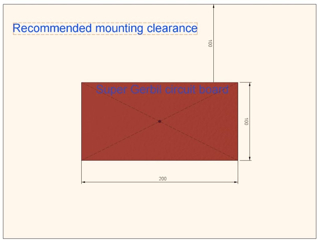
Physical Mounting
Good physical mounting of the Super Gerbil not only preserves valuable bench space but it also protects the Super Gerbil from tools, material, dust and vibrations. The recommended minimum mounting dimensions to allow access to screw terminals and line-of-sight to wire insertion into the screw terminals are:
Here’s an example mounting [dan insert Nomad photo]
Do not install the Super Gerbil on or near flammable material or moisture sources.
Electrical wiring
The Super Gerbil CNC controller circuit board consists of 4 areas with connectors/screw terminals:
[Paul, split Area 1 into 1A and 1B. 1B is the USB rightwards, so that it is functionally distinct from the Limit Switch related stuff
Also split Area 3 so that the Control Vin is part of Area 2].
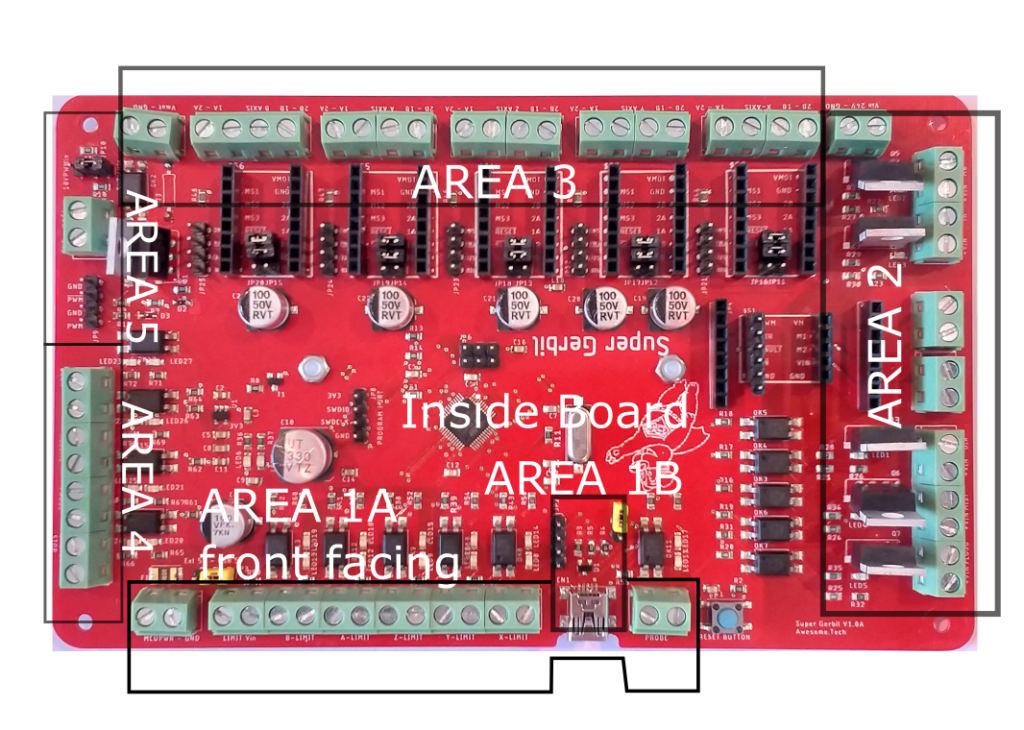
The roles of the different areas are:
Area 1A – connects to your CNC’s limit / probe switches and power supply input so that your machine can home and probe properly
Area 1B – connects your Super Gerbil CNC controller to your computer via the USB or UART/BlueTooth connection. This area also features the UART header and comms switch jumper
Area 2 – the Output ports cover driving your actuator (such as a CNC spindle or laser), cooling (Flood and Mist) and Tool Change (Tn, M6) and its power supply input
Area 3 – connects to your CNC’s stepper motors and 24V DC fan, including the main power supply for them
Area 4 – connects to controller terminals, like Pause, Abort etc and uses the same power supply input as the limit/probe switches
Area 5 – PWM output port for external VFD drives with its power supply input and power selection (5 or 10V)
Area 1A Connections – Limit Switches
Bring the limit switch wiring for your machine to the Area 1 terminals, with the power supply connecting to the left most two terminals. Here are some example wiring diagrams:
The Limit switch and Control opto couplers are powered via the Limit Vin power screw terminal. Connect a power supply to this (any power between 12-24V). There is no power polarity on the Limit Vin so any way connection of plus and ground (referred as GND) is fine. There are two LEDs per port so that an indication is made regardless of the polarity.
Connect each limit switch (Normally Closed) to the appropriate terminal. For example, the Limit Switch that indicates the start (or end) of your X direction movement should be wired to the X limit switch terminal.
Note: the standard configuration for limit switches is Normally Closed to prevent accidents when wiring is broken and undetected. The disadvantage of Normally Open wiring is that you would NOT notice or detect a wire defect until the machine hits an end position and fails to stop. At least with a Normally Closed configuration, any wiring fault is immediately detected when the unit is turned on.
The Probe is the opposite of limit switches: Normally Open.
Hint: a probe switch can be easily made out of a piece of PCB board and a crocodile test wire lead. ‘G38.2 Z-1 F5’ will auto probe the tool on the work piece or bed and just enter the PCB thickness as the Z offset, and you’re done!
Area 1B Connections – USB
Plug in the USB cable, but do not connect to your PC yet. (115200 Baud rate)
The small Reset button can be used to reset the Super Gerbil, however this should not generally need to be used. The only standard use of this button is for programming the board with updated firmware (referred as flashing the board).
NOTE: using this board for a laser requires a change in baud rate to 230400 to allow high speed engraving. Just let us know when you order online!
Area 2 Connections – Output Terminals
Note: If you don’t have peripherals or want to install them later then you can skip this step.
Five MOSFET ports: Flood, Mist, Spindle Vin/Motor, Tn, M6
The Output terminals are used to drive your Mist or Flood devices. More generally, then can be used to control any auxiliary DC relay or motor/pump or ATC. They are powered from the Vin screw terminal labeled on the silkscreen as “Vin 24V – GND Mosfet ports”. Connect the load on each appropriate terminal.
The TN and M6 terminals are used for external automation e.g. Automatic Tool Changer. It’s beyond the scope of this instruction and a separate blog will be used to explain this in more detail.
Note that all the above terminals use MOSFETs, and thus require protection from inductive spikes. Specifically, a diode has been mounted on the Super Gerbil PCB in anti-parallel to protect the MOSFET (no external diode required).
The spindle DC brushed motor has 4 connections: M1 and M2 are the motor terminals. The Vin motor and Ground are the power inputs for the Motor driver board that sits in the socket behind the terminals.
Based on which Super Gerbil product you ordered, you will have either a 150W and 750W Brushed DC motor controller. The 750W unit also has optional terminal pads on the motor driver itself that can be used instead of the screw terminals, however we recommend for clean installation to use the screw terminals on the Super Gerbil.
Other motor types (above 750W, Brushless DC etc) must be driven of the PWM opto coupler port on the opposite side of the board (See area 5).

Connect the Vin terminal. Pay attention to the polarity of the wires plus/positive and GND.
Area 3 Connections – Stepper Motors
Super Gerbil board power input – is the two input terminal shown on the left of Area 3. This power input is used to supply your Stepper Motors, and can range from
- Limit Vin, Limit switches X to B, USB connector, Probe and reset button (we call this the front in this instruction for reading purposes)
- Vin for Ports(2), Stepper motors X to B, Vmot stepper power in
- PWM power jumper selection, Vpwm in, Door, Resume, Pause, Emergency button connections.
Area 4 Connections – Control Buttons
These connections allows you to add external push buttons for the Pause and Resume functions, a door switch for your CNC enclosure and the emergency button (Abort).
Area 5 Connections – Spindle PWM port or VFD drive connection
You can use this optocoupler port to drive an external peripheral like a Brush-less DC motor driver or VFD.
The 4 pin PWM header has a positive and a negative or complementary output. This can be used for lasers where it is common that the low signal switches on the laser and a 5V signal stops the laser beam. For brush-less motor drivers it is more likely that it uses the positive logic where 5V turns the motor on and 0 turns it off.
The screw terminal block is where you apply the power supply either 5 or above 10 Volt. The jumper above the screw terminal allows you to use the on-board zener diode to regulate the level to 10V because this is a common interface logic level standard among VFD drives.
Area 5 Connections – Laser PWM port
You can use this optocoupler port to drive a Laser power supply port.
The 4 pin PWM header has a positive and a negative or complementary output. This can be used for lasers where it is common that the low signal switches on the laser and a 5V signal stops the laser beam.
Connect the Negative PWM output to the IN port terminal on the Laser power supply and the GND pin to the GND or Ground terminal on the laser power supply.
Configuration Jumpers and Headers
The middle of the board has (facing the front of the pcb or usb port):

- Breakout pins for each stepper
- Jumpers for micro step selection within each step stick socket
- Optional boot selection
- Two motor sockets for small or big DC brushed spindle motor driver
- Programmer port (4 pin header)
- Ext 5V or USB power jumper selection for the STM32 processor selection
- UART 4 pin header for the Blue Tooth dongle
- jumper for USB or Bluetooth communication choice
(closed=BT – rapid flashing of heartbeat led7, open=USB – slow flashing of heartbeat led7, BT pairing pin=”1234″)
We will go into detail for each item to provide you with installation instructions and options.
Breakout pins for each stepper
There are 4 pins available to drive an external motor driver:
DIR – direction for the external motor driver
STEP – the step pulse or clock for the external motor driver
ENA – Enable (negative logic) or chip select for the external driver. A logic 0 or low enable the motor driver. This can be inverted in the firmware ($$).
GND – The ground signal level for the external driver
Jumper micro step settings
The jumpers are used to select the micro steps and the compatibility.
The Compatibility pin is the header closest towards the edge (terminals) of the PCB. The silkscreen has a label-box and little arrow pointing at it.
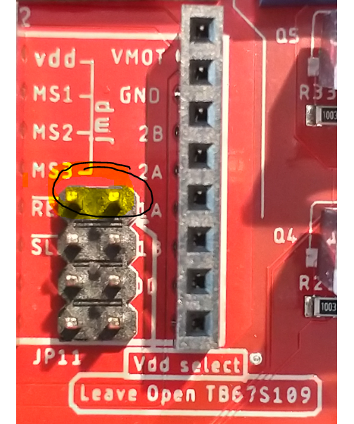
The TB67S109 has an 5V output pin while the A4988 has a 5V input pin. Only bridge the compatible pin for 5V input. Bridging this pin on 5V output will clash 5V levels and might cause damage to either stepper or processor. We have tested this and both stepper and processor survived but better be safe than sorry (remove the jumper bridge for TB67S109).
Micro-steps settings are noted on the PCB. The board for the Gold and Silver tiers has been configured for 1/8th step and compatibility pin = open. You can change the steps by changing/adding jumpers. $100 – x axis, $101 – Y axis and $102 – Z axis has been set to 80 steps. Moving to 1/16th requires you to double these steps to 160 etc. The TB67S109 supports up to 32 micro-steps but unlikely to be used.
Optional boot selection
Future use: This is to allow to boot and use the Arduino IDE. NOTE: No boot loader has been flashed so not necessary to jumper these. For the moment we use the default free Atollic TRUE Studio for STM32.
Two motor sockets for Spindle
This to allow a choice of motor driver (MAX14870 Single Brushed DC Motor Driver Carrier or Pololu G2 High-Power Motor Driver 18v25). If you use an external driver via the PWM pin header then you can leave the socket empty or in place). The small pololu MAX14870 takes max 36V while the G2 driver takes max. 30V. See links for detailed specifications.
The Spindle driver has M1,M2 as motor output connections and +Vin and GND as external power supply input terminals.
The PWM Spindle frequency can be set via $28 in the firmware (upto 80kHz $28=15).
Look up the silkscreen on the driver to insert the driver into the socket in the correct position. The PWM pin should face inwards (centre of the PCB) while M1,2 should face outwards (edge of the PCB).
Programmer port
The programmer port can be used to flash a new firmware. It takes 3V3, SWDIO, SWCLK and GND from the supplied ST LINK V2 dongle. Some dongles do have swapped SWDIO and SWCLK labels. When connecting via the ST LINK software, you need to click on connect and quickly hit the reset button on the Super Gerbil. It’s tricky but you get the hang of it. This is required because the SWDIO and SWCLK are multiplexed function pins that are re-assigned to other pin functions when the firmware starts. The firmware is not read protected so you can read out the current firmware as a backup.
The STM32 ST-LINK Utility (STSW-LINK004) can be downloaded from the ST.com website here and the legacy VCP com port drivers (for old OS’s) here.
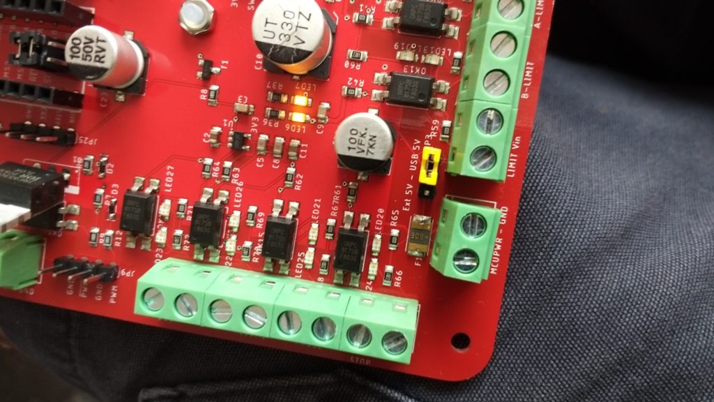
Ext 5V or USB power jumper selection
This pin is to select how to supply power to the processor. It can be powered via an external 5V or via the USB cable/PC.
Ensure when using ext 5V selection that you have a proper stabilized 5V/300mA power supply. An internal circuit does convert this to 3V3 and it can handle some input power fluctuations.
UART Header
This 4 pin header is used to connect to the BT module (HC-5, 6 or equivalent). Unfortunately the pin assignments on the silkscreen are covered by the white header connector.
- Pin 1 – 3V3
- Pin 2 – TX (which is RX of BT module)
- Pin 3 – RX (which is TX of BT module)
- Pin 4 – GND
The module has been configured with a SSID ‘SuperGerbil’ with PIN-‘1234’ and baud-rate of 115200.
The baud-rate can be increased up to 230400 in the BT module and Firmware (main.c, however the firmware needs re-flashing). Some BT modules only support up to 115200.
USB/BT jumper
This pin is to select which communication channel is being used to interface : USB or BlueTooth.
An open pin stands for USB and closed for BT. THe heart beat led7 does show when USB mode (slow beat) or BT mode(fast) is selected. When changing a mode via a jumper, a reset via the reset button on the Super Gerbil is required.
Controls and Limit terminals
Both Controls and Limit switches opto interfaces are supplied via the LIMIT vin power terminal. It is polarity indifferent and two leds are mounted for each connection to deal with reversed polarity.
Limit switches are configured as NC – Normally closed. This can be inverted with the firmware configuration $5 (See here for codes)
The Control buttons are NO – normally open since buttons are usually NO. To change this to NC, you need to reflash the firmware (in module system.c, change controls to NC).
NOTE: The emergency button (aka Abort or Reset) is a separate control not related to the hardware reset button next to the USB port although this name is frequency used in Arduino forums.