
“All you ever wanted to know about limit switches and homing”.
First things first
The rest of this article assumes that your machine’s basic directional wiring and configuration is such that sending a left jog command from your computer’s software moves your gantry left, and similarly for right, up and down. With this baseline, you can proceed with setting up homing and limit switch configuration.
Defining home with $ settings configuration
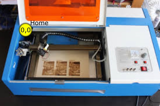
The K40’s home and limit switch position is in the back-left corner. Other machines have different home positions and/or limit switch positions.
The Mini Gerbil product comes pre-configured for the standard back left home and limit switch position. If you want a different home or limit switch position, the configuration involves two $ settings:
- $3 direction of travel, and,
- $23 direction of homing
Confusion can occur because the $23 direction of homing is relative to the $3 direction of travel. So, even if you just change $3, the direction of homing will also change in effect.
The best thing to do is to set the direction of travel ($3) first and, once that’s right, then change $23 if necessary to set the homing direction.
Various limit switch configurations
There are various physical limit switch configurations for the different lasers in the market. The K40 falls under configuration I while others fall under II, III or IV. The most common configurations are I and II.
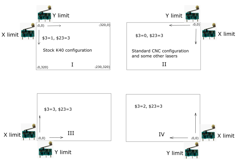
$3 and $23 work with a bitmask where the first digit is for the X axis and the second digit is for the Y axis (e.g. MASK ‘YX’ – ’00’=0, ’01’=1 which is X set, ’10’=2 which is Y set, ’11’=3 which is both X and Y set).
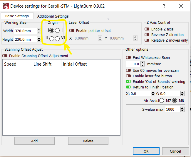
The final step is to ensure that your software tool knows your machine’s physical setup. In this example, LightBurn has a menu which shows four alternative configuration positions for the origin (home). You should match the corner in the software, with your physical setup.
Errors during homing
‘Pull-off’ refers to the distance between a limit switch’s ON position and a limit switch’s OFF position. If you carefully click a limit switch on/off, you’ll hear the contacts click at different positions. More generally, this characteristic is known as hysteresis and is a deliberate design to enhance stability.
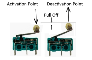
CNC systems, including the K40, find the home position, then reverse back the pull off distance, so the limit switch has just de-activated. This position is defined as home.
There are multiple versions of the K40 laser cutter.
- The Mini Gerbil is configured to suit K40’s with ribbon cables which have electronic limit switches, with a pull off distance of 2.5mm
- If you’re using a different machine, for example with mechanical limit switches, then you’ll need to set a 4mm distance by $27=4
An error during homing, such as Error 8, occurs when the configured pull off distance is less than the switch’s actual pull off distance.
Error 8 occurs if the $27 setting is set to 2.5mm and the physical pull off if (say) 4mm, because the controller is expecting that the limit switch to be deactivated at a distance of 2.5mm, but it is still activated.
Error 9 occurs when the controller does not receive a signal from the limit switch, or the limit switch is bouncing too long. In the case of a bouncing limit switch, increase $26 to an appropriate value e.g. 125.
Other complexities
There are further possibilities that may apply in unusual circumstances. For example, it’s possible to set up limit switches at both ends of a gantry. Please email us for support on these matters.
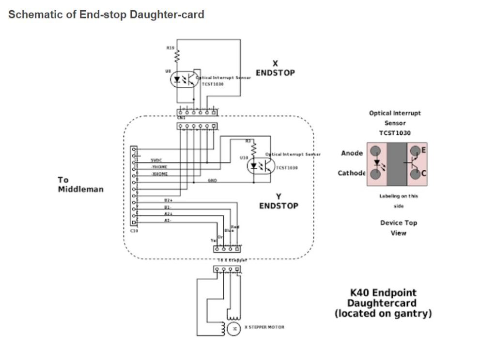
Schematic of the K40 limit switches
The limit switches can fail with age. The stock limit switches do have each a 1kOhm resistor mounted which is too high in value to work in the linear range of the slot optocoupler causing non-logic values. Better are values between 100 and 390 Ohms. Below the schematic of the limit switches in the K40. The x – limit is hidden below the gantry bar on the left side. The Y limit is on the left top gantry and is directly visible.
About us
We sell the Mini Gerbil 2 axis laser controller to make your K40 upgrade or custom laser project easy. We’re constantly reviewing our hardware, firmware, software, testing, customer support and instructions to achieve that goal. We look forward to your questions/comments below on this blog.
The working of a limit switch can be checked via the question mark command. Just enter ? into the LB console or issue this via a g code sender and the MG replies with it’s status. When engaged you will see something like Pn=X (x axis engaged).