
This section covers detailed configuration changes possible by using jumper pins on the Super Gerbil board.

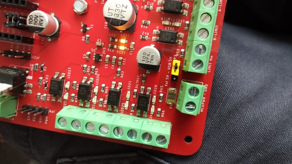
For orientation, working clockwise around the board, starting from the top right white boxed area:
- Stepstick microstep jumpers allow configuration of microsteps for each stepstick and step stick compatibility
- USB/Bluetooth jumper allows communication choice between USB or Bluetooth. To select Bluetooth, bridge the two pins with the jumper. Observe the rapid flashing of the heartbeat LED 7 (towards left hand side of board). Use ‘1234’ as the PIN code for Bluetooth pairing on your device. Alternatively, for USB, open the bridge so that the two pins are not connected. LED 7 should flash slowly. The USB driver should install by itself under WIN10. If not or older OS versions, please install the appropriate VCP driver from STMicroelectronics.
- Bluetooth module 4 pin connector (UART). For Bluetooth operation, ensure the bluetooth dongle is connected to these four terminals. The socket is polarised.
- USB/MCU jumper provides a choice in how the Super Gerbils STM32 micro-controller is powered. It can either be powered by the USB of the connected computer, or via an external 5V supply. If you’re using Bluetooth, you’d need to select and supply 5V (unless you keep a usb cable plugged into the Super Gerbil).
- Programmer port (4 pin header) – this is used if you need to update the Super Gerbil’s firmware.
- Boot jumpers (not used but in case you install a boot loader)
- Breakout pins for each stepper – can be used as an alternative to the main stepper terminals, as a way of accessing the stepper motor drive signals.
Also shown towards the Right Hand Side of the photo are two motor sockets for small or large DC brushed spindle motor driver
We’ll now detail each item:
Breakout pins for each stepper motor
The ‘Innovator’ (Gold) and ‘Maker’ (Silver) Super Gerbils have Toshiba stepsticks which are capable of 4A load. A ‘Starter’ (Bronze) Super Gerbil uses A4988 stepsticks, capable of 1.5A load. If these are not enough for your purposes, you’ll need an external stepper motor driver, connected to the relevant breakout pins:
- DIR – direction for the external motor driver
- STEP – the step pulse or clock for the external motor driver
- ENA – Enable (negative logic) or chip select for the external driver. A logic 0 or low enable the motor driver. This can be inverted in the firmware ($$).
- GND – The ground signal level for the external driver
Stepstick micro-step jumpers
The jumpers are used to select the micro steps of the stepper motors.
Micro-steps settings are printed in a table on the PCB. The Gold and Silver version of Super Gerbil has been configured for 1/8th step. You can change the steps by changing/adding jumpers and the relevant controller setting. For example: $100 – x axis, $101 – Y axis and $102 – Z axis has been set to 80 steps. Moving to 1/16th step requires you to double these steps to 160 etc. The TB67S109 supports up to 32 micro-steps but this extreme value is unlikely to be used.
Stepstick Voltage Jumpers

The Voltage Compatibility pin is the header pin closest towards the edge (terminals) of the PCB. The silkscreen has a label-box and little arrow pointing at it. The voltage compatibility pin is necessary because the TB67S109 Step stick has a 5V output pin, whereas the A4988 has a 5V input pin. Thus:
- Bridge the jumper for compatibility with the A4988’s 5V input pin, OR
- DO NOT bridge the jumper for compatibility with TB67S109’s 5V output pin. If you keep the bridge in place, the 5V levels will clash and this may cause damage to either stepper or processor.
The Gold and Silver version of Super Gerbil has compatibility pin = open to support the TB67S109 which has a 5V output instead of input pin. Bronze versions have been configured for A4988s (compatibility pin = closed).
Optional boot selection
Future use: This is to allow to boot and use the Arduino IDE. NOTE: No boot loader has been flashed so not necessary to jumper these. For the moment we use the default free Atollic TRUE Studio for STM32.
Two motor sockets for DC Spindle drivers
These sockets allow a choice of motor driver (MAX14870 Single Brushed DC Motor Driver Carrier or Pololu G2 High-Power Motor Driver 18v25). If you use an external driver via the PWM pin header then you can leave the socket empty. The small pololu MAX14870 takes max 36V while the G2 driver takes max. 30V. See manufacturer’s data sheets for detailed specifications.
The Spindle driver has M1,M2 as motor output connections and +Vin and GND as external power supply input terminals.

Look up the silkscreen on the driver to insert the motor driver into the socket in the correct orientation. The pins labeled PWM, DIR, EN/CS should face inwards (centre of the PCB) while motor outputs labeled M1,2 should face outwards (edge of the PCB).
The PWM Spindle frequency can be set via $28 in the firmware (up to 80kHz 80kHz is configured as $28=15).
- 0 = 60 Hz
- 1 = 120 Hz
- 2 = 250 Hz
- 3 = 500 Hz
- 4 = 1 kHz (configured as default)
- 5 = 1.5 kHz
- 6 = 3 kHz
- 7 = 4.5 kHz
- 8 = 6 kHz
- 9 = 8 kHz
- 10 = 10 kHz
- 11 = 15 kHz
- 12 = 30 kHz
- 13 = 45 kHz
- 14 = 60 kHz
- 15 = 80 kHz
Note: other frequencies are possible via firmware changes.
Programmer port
The Super Gerbil’s in circuit programmer port can be used to flash a new version of the firmware. The steps are:
- Download and install the STM32 ST-LINK Utility (STSW-LINK004) from the ST.com website here and the legacy VCP com port drivers (for old OS’s) here.
- Connect the supplied ST LINK V2 dongle to the Super Gerbils’ labelled pins: 3V3, SWDIO, SWCLK and GND. Some dongles have swapped SWDIO and SWCLK labels, so if it doesn’t work one way, try the other.
- Unplug the USB between your PC and SuperGerbil.
- Connect your PC to Super Gerbil via the ST LINK software: click on ‘connect’ and quickly hit the reset button on the Super Gerbil. It’s tricky but you get the hang of it. This is required because the SWDIO and SWCLK are multiplexed function pins that are re-assigned to other pin functions when the firmware starts. The firmware is not read protected so you can read out the current firmware as a backup.
- Follow instructions (to be provided) regarding uploading new firmware.
Ext 5V or USB power jumper selection
This pin is to select how to supply power to the processor. It can be powered via an external 5V DC supply, or via the USB cable/PC.
Ensure when using the ext 5V DC selection that you have a proper stabilized 5V/300mA power supply. An internal circuit converts this to 3V3 and it can handle some input power fluctuations.
UART Header
This 4 pin header is used to connect to the BlueTooth (BT) module (HC-5, 6 or equivalent). Unfortunately the pin assignments on the silkscreen are covered by the white header connector. They are:
- Pin 1 – 3V3
- Pin 2 – TX (which is RX of BT module)
- Pin 3 – RX (which is TX of BT module)
- Pin 4 – GND
The module has been configured with a SSID ‘SuperGerbil‘ with PIN-‘1234’ and Baud-rate of 115200.
USB/BT jumper
This pin is to select which communication channel is being used to interface : USB or BlueTooth. An open pin configures for USB and closed for BT. The heart beat LED7 displays the communications mode USB=slow beat, BT=fast beat. When changing a mode via a jumper, a reset via the reset button on the Super Gerbil. To install the BT usb communication on your PC or Laptop See https://supergerbil.com/2019/06/using-bluetooth-comms-via-pc/
Controls and Limit terminals
Both Controls and Limit switches optocoupler interfaces are supplied via the LIMIT Vin power terminal. It is not polarised: two optocoupled LEDS are connected in anti-parallel so as to support either + and – polarity.
Limit switches are configured as NC – Normally closed. This can be inverted with the firmware configuration $5 (See here for codes)
The Control buttons are NO – normally open since buttons are usually NO. To change this to NC, you need to reflash the firmware (in module system.c, change controls to NC).
NOTE: The emergency button (aka Abort or Reset) is a separate control not related to the hardware reset button next to the USB port although this name is frequency used in Arduino forums.
USB Baud rate
The default rate for the Super Gerbil is 115200. If you’re using this board for a laser requires a change in baud rate to 230400 to allow high speed engraving, let us know when you order online.
Hello from Germany,
if you insert following lines in “protocol.c”, then the software LaserWeb will recognize the version.
To see the virtual tool parameter $10 must be set to 0.
line 102
} else if (line[0] == ‘$’) {
// Grbl ‘$’ system command
report_status_message(system_execute_line(line));
} else if (sys.state & (STATE_ALARM | STATE_JOG)) {
// Everything else is gcode. Block if in alarm or jog mode.
report_status_message(STATUS_SYSTEM_GC_LOCK);
}
insert these lines…
else if ((line[0] == ‘V’) && (char_counter == 7))
{ // Check for “version” command, write hello message if so
report_init_message();
}
else
{
// Parse and execute g-code block.
report_status_message(gc_execute_line(line));
}
…
Greetings from Germany
Udo
Are there additional plans for supergerbil?
Hi, we are creating a new controller with SD card and Display! Check it here soon.
Good news
Is any chance that you use the STM32CUBEIDE environment?
As we know STM32CUBEIDE is the standard IDE that ST invests and is the successor of Atollic then TrueSTUDIO for STM32 then STM32CUBEIDE.
So its good to see SuperGerbil software for your new board inside STM32CUBEIDE.
waiting for the new board.
Thanks a lot
Vasilis
So this was a long while ago – I’m guessing that (at best) this stalled, but is there any word for future plans?
Yes we have developed a new 6 axis board with display, vacuum, and distance measuring but it’s in its test phase. Many new firmware options to set ports/tools M10 etc.