
The MG3 and its LED indicators are shown below, followed by a description of each. The LEDs may be referred to during troubleshooting and when requesting support.
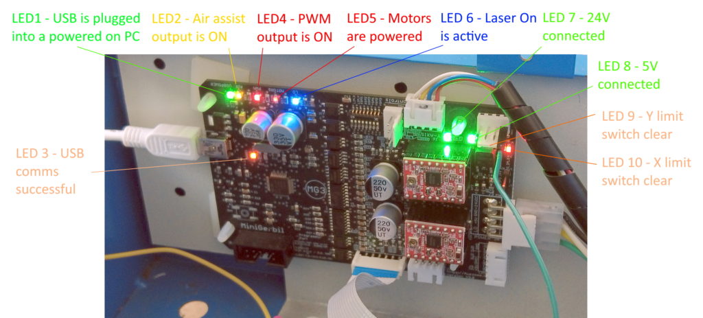
LED1 – Green – USB power – illumination indicates the USB cable is plugged into the cold side. Note this is a separate function to the communications LED3.
LED2 – Yellow – Air Assist – illumination indicates the air assist function is operating (M7 command). Turned off via M9 command. Alternative configurations are possible, see (link)
LED3 – Orange – USB Communications – flashing indicates the Mini Gerbil is attempting to connect to the PC. Continuous illumination indicates communication is successful.
LED4 – Red – PWM (laser strength) – illumination indicates the Mini Gerbil is outputting a PWM signal to fire the laser. The brightness of the LED does not indicate the PWM intensity. Note: due to a firmware limitation, LED 4 turns on in coordination with LED 6, even if the PWM output is zero. This issue has been noted and may be addressed in future firmware releases.
LED5 – Red – Motor movement – illumination indicates the Mini Gerbil is attempting to operate the motors.
LED6 – Blue – Laser On (LO) – illumination corresponds with the LO signal being in active state. Alternative configurations e.g. positive logic, are possible, see (link)
LED7 – Green 24V – illumination confirms that 24V is connected to the Mini Gerbil hot side.
LED8 – Green 5V – illumination confirms that 5V is connected to the Mini Gerbil hot side.
LED9 – Yellow Y limit switch – illumination indicates the Y limit switch is NOT engaged
LED10 – Yellow X limit switch – illumination indicates the X limit switch is NOT engaged
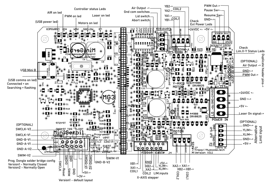
Note: -> means output, <- input, <-> common
Two programming dongle versions are supported (version1,2)