
This page details
- Air assist setup / connection
- Micro step settings available via DIP switches
- Limit switch configuration available via DIP switches
- Safety Door / Lid connection
- Emergency stop / Abort connection
- Pause/Resume connection
- Communications baud rate
- USB plug
- Power connections
Air assist setup
The following diagram shows a typical air assist wiring:
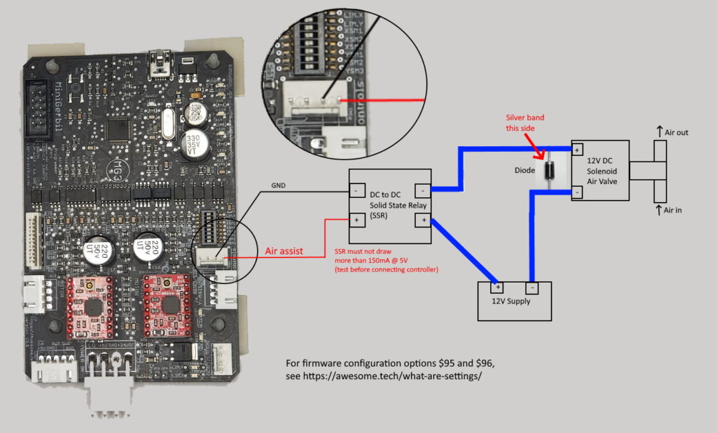
The MG3 has an air assist output, capable of sourcing or sinking current. Before connecting to your MG3, test that your SSR draws no more than 150mA on the input side. The MG3 can source or sink up to 150mA current to drive the SSR. The MG3 should only be used to drive SSR, not coil based relays.
The what are $ settings page describes various air assist configuration options, including:
- $95 – air assist configuration (standard/invert)
- $96 – pause air assist during job pause. Resumes air assist when job resumes
G-code can be used to control the air assist in two ways:
- standard (M7/M9), and
- advanced configurations (M8/M9). See https://awesome.tech/mg3-air-assist-customisation/
Please contact support@awesome.tech if more information is required.
Air assist connection
The Air assist output pin is located on the connector header J2 – Pin 1. It can be used in combination with ground J2 – Pin 2.
Note The Air assist pin must not be shortened to 5V or Ground.
The air assist output is designed to drive a Solid State Relay (SSR) and has the following logic levels: 5V for 1 and 0V DC for 0.
An alternative connection to J2 – Pin 1 is the spare pin header JP4 (next to the spare PWM output pin JP3 and power connector J3). JP4 is connected to J2-Pin 1 and is provided for easy wiring and access.
Note that the MG3 can operate without air assist, and when commissioning a new MG3, it is wise to get basic operation working without air assist. Once that is proven, then procced to wire in air assist.
See MG3 Air assist for debugging advice.
DIP switch overview
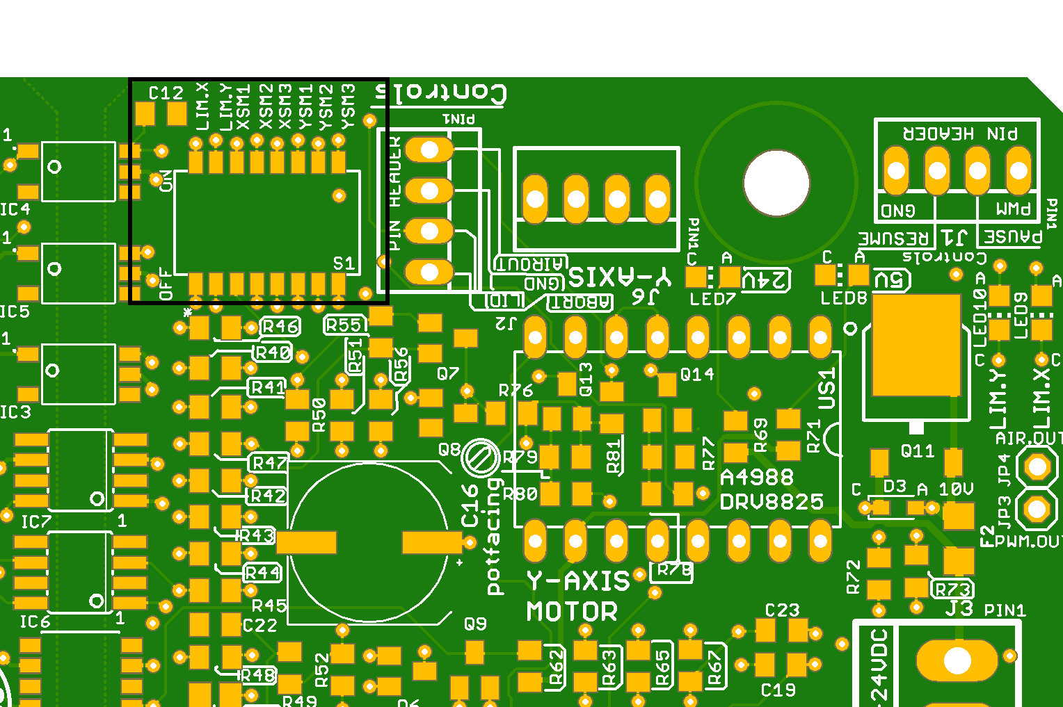
The microstep configuration and limit switch pull up resistor configuration are both on one mini DIP switch located at the edge of the hot side, see top of image below. To set the DIP switch to ON, the tiny white tab should be towards the outside of the board. To set the DIP switch to OFF, the tiny white tab should be towards the inside of the board.
Microstep settings
Simply set the DIP switches according to the table below. Configure matching settings in $100 for the X axis and $101 for Y axis. E.g. 1/16 step requires 157 microsteps. So moving to 1/8 step should half the $100 and 101 settings to 78 etc. Depending on the machine and belt settings these numbers could be slightly different. Usually lasering test square of 100x100mm gives you a good reference. If the square is oversized that reduce the microstep setting $100/101 e.g. 157 to 156 etc. If too small then increase the setting. Default is 157 microsteps.
Note: The table assumes identical step settings for both axes. However you can run each axis on different microsteps if your use case requires that e.g. X axis on 1/8 and Y axis on 1/16. Below are the settings for the A4988 and DRV8825 step stick drivers.
| Step configuration | XSM1 | XSM2 | XSM3 | YSM1 | YSM2 | YSM3 | Related $ setting |
| Full step | OFF | OFF | OFF | OFF | OFF | OFF | $100,101 |
| 1/2 step | ON | OFF | OFF | ON | OFF | OFF | as above |
| 1/4 step | OFF | ON | OFF | OFF | ON | OFF | as above |
| 1/8 step | ON | ON | OFF | ON | ON | OFF | as above |
| 1/16 step | ON | ON | ON | ON | ON | ON | $100/101=157 |
| Step configuration | XSM1 | XSM2 | XSM3 | YSM1 | YSM2 | YSM3 | Related $ setting |
| Full step | OFF | OFF | OFF | OFF | OFF | OFF | $100,101 |
| 1/2 step | ON | OFF | OFF | ON | OFF | OFF | $100/101=20 |
| 1/4 step | OFF | ON | OFF | OFF | ON | OFF | $100/101=40 |
| 1/8 step | ON | ON | OFF | ON | ON | OFF | $100/101=79 |
| 1/16 step | OFF | OFF | ON | OFF | OFF | ON | $100/101=157 |
| 1/32 step | ON | ON | ON | ON | ON | ON | $100/101=314 |
Note: the DRV8825 has low torque in 1/32 step setting and does not work reliably on a typical K40. So for the DRV8825 we advise to use settings between full step and 1/16th only.
Limit switch settings
The DIP switches enable/disable the MG3’s 4k7 pull up resitor for each limit switch input.
If your external limit switch already has a pull up resistor on its outputs, then the MG3’s pull up resistor in parallel may stop the limit switch outputs achieving a logic LOW. In this case, disable the MG3’s 4k7 pull up resistor. Limit switches do have a LED status on the MG3 see MG3 LED indicators.
| Limit configuration | LIM.X | LIM.Y |
| PULL UP enabled | ON | ON |
| PULL UP disabled | OFF | OFF |
Limit switch connection J4 or J5-Pin3/4
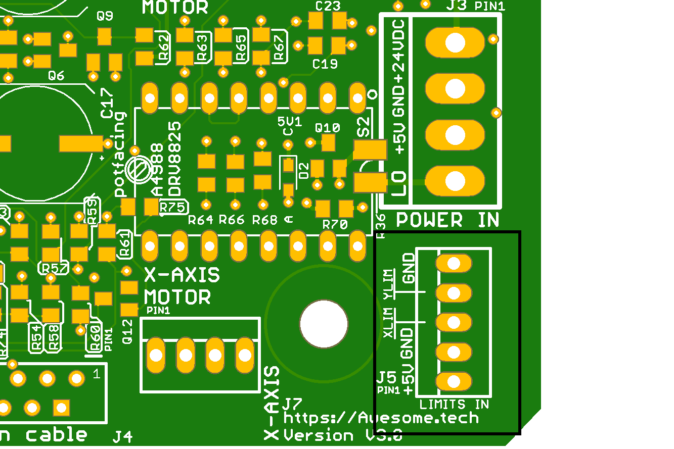
The limit switches are wired up via the connector J5 (see marked up connector on the corner edge below). Make sure that limit switch cabling is neat and separated from other cables to avoid electrical noise and interference. ideally use shielded wiring. The connector layout matches that of the K40 laser limits connector and the keyed connector prevents reversed plugin.
Note that these limits are also available on the k40 ribbon cable connector. K40 lasers either have
- a ribbon cable with Y axis motor cable OR
- limits cable, X and Y axis motor cables.
Other lasers may use individual connectors for limits and motor axes.
| PIN number | Function |
| 1 | +5 V DC – not used with the K40 |
| 2 | GND |
| 3 | X Limit |
| 4 | Y Limit |
| 5 | GND |
Safety Door switch settings
$97=1 enables the Safety Door switch feature and $97=0 disables it (for debugging purposes).
Note MG3 can operate without the Safety Door and added later when the user is familiar with the machine.
Safety Door switch connection J2-Pin 3
The Safety Door gets activated when the pin is grounded. The Safety Door pin is call Lid on the PCB silkscreen and located on connector header J2 – Pin 3. The Ground GND on J2 – Pin 2 can be used with this connection. The easiest way to set up a lid switch is to use a micro switch in NC – normally closed configuration. When the lid closes it engages the micro switch which opens the connection. Only with a closed lid can the MG3 execute the G-code stream. The enquiry command ‘?’ does provide info when the Safety Door is engaged. By setting $97=0, the user can override the Safety Door (handy for setting it up).
Emergency button connection J2-Pin 4
The Emergency button can be hooked up to the MG3 via connector header J2 – Pin 4. The emergency (aka Abort) can be activated when the Abort pin is grounded (J2 – Pin 2 Gnd). The MG3 stops all action and the user needs to home the machine to restart the job or unlock it via $X (machine stays at the point where it stopped).
Note MG3 can operate without the emergency button and the feature can added later.
Pause/Resume connections J1-Pin2/3
Pause and Resume buttons can be added to the controller to pause the laser job execution. Not all laser application have the logic to synchronise the software application pause and resume buttons with the state of the controller. It might be possible that you cannot use a physical button to pause and use the software button to resume (just use only the physical buttons or software). The Pause pin is located on connector header J1 – Pin 2 and Resume is located on the same header at Pin 3. The activate when grounded (J1 – Pin 4 – Gnd). Use momentarily push buttons (not latching buttons). MG3 can operate without physical pause/resume buttons and added in a later stage.
Note that pause is not immediately (the g-code stream buffer is emptied first). On a small job e.g. rectangle you might not be able to pause due to the small g-code that fits entirely in the buffer.
Baud rate settings
The MG3 does not need any Baud rate configuration since the USB driver automatically selects its best and fastest baud rate via “On The Go” (OTG) technology when the USB cable is plugged into the computers USB port. Any configuration you do on the WIN driver on the computer (Device Manager) is not relevant. For example, you might see a setting of 9600 baud, but this value is overridden by OTG.
USB plug
The MG3 requires a mini B USB cable.
The MG3 draws around 100mA from the USB to power to the microcontroller on the cold side.
Power connections
The MG3 is powered by
- 24V DC for the stepper drivers and
- 5V DC for the limit switches, controls, air assist and PWM pins.
Both voltages are supplied via the big four pin MTA156 connector on the MG3’s hot side.
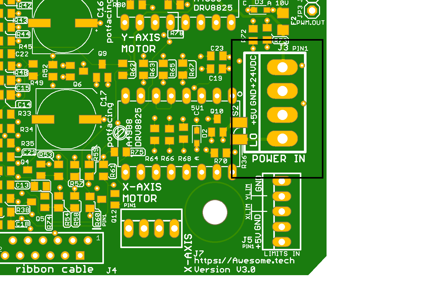
| PIN | Label | Description |
| 1 | +24V DC | Power supply for Stepper Motors |
| 2 | GND | Common ground |
| 3 | + 5 V DC | Power supply for Limits, Controls, air output |
| 4 | LO | Out pin for ‘Laser On’ enable signal (Low level is on, High is off) Logic can be inverted via $ setting 99 |