
Congratulations if you’ve got the PPA going, it was a real challenge. Are you ready to take it to the next level and pull a vacuum?
Ok, so pulling a vacuum is exaggerating somewhat, but even if we can reduce air pressure by 80% of atmospheric (from 101kPA to 20kPA) that should give us a pretty good indication about the contribution of air resistance to our friend the rotating ball. More scientifically speaking, by measuring the air pressure and plotting ball speed at each pressure, it should be possible to estimate the drag coefficient for the ball.
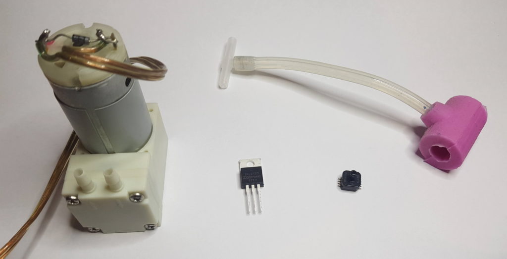
The design idea is to use a cheap 12V vacuum pump, fitted with a custom vacuum flange, and flexible silicone or vinyl tubing. The vacuum pump will be controlled by a MOSFET on the Output board, which is in turn controlled by the Arduino. A T-piece connector will extend the vacuum to an electronic vacuum sensor that is mounted on the throttle. The sensor’s output is connected back to the Output board, where it is interfaced to the Arduino and the vacuum pressure can be read by the Arduino firmware. From there, it can easily be displayed on the screen to inform the user.
While controlling the vacuum pressure via software presents a wide range of opportunities, the default design is to utilise one of the throttle buttons as an on/off switch for the vacuum pump. Thus the button is a ‘soft switch’, in that it operates via the software on the Arduino, rather than directly controlling the vacuum pump energisation.
One challenge we can anticipate is that vacuum pumps, especially at the economy end of the market that we’re dealing with, are imperfect. When not in operation, they only partially block air seeping back into the vacuum. To address this, we can add an electrically powered pneumatic valve. When the desired degree of vacuum has been reached, the pump should be stopped and the valve engaged to block the reverse air flow. Of course the valve isn’t perfect either, but it will certainly extend the duration of the vacuum significantly.
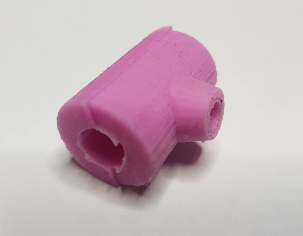
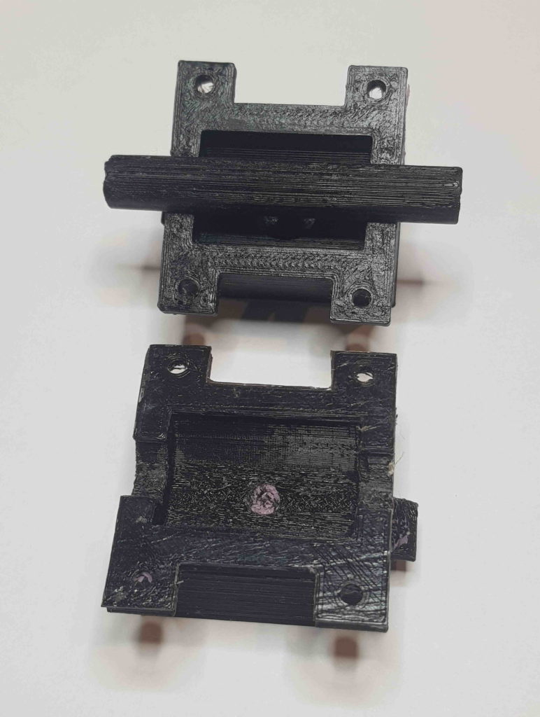
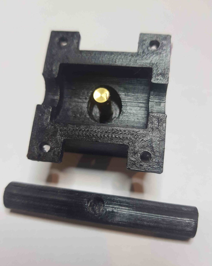
The fabrication of the custom vacuum flange is a new and interesting exercise. What material would be suitable and how might it be formed? After investigating a number of options, I settled on fabricating the vacuum flange from two-part silicone molding mix. Of course the necessary shape still had to be defined, so I designed the flange in CAD, and then formed a negative in CAD as well. As the flange is essentially a shell that allows air to flow through it, the geometry is a little complex. The mold consists of three 3d printed parts (two halves, and a 3d printed rod), and a small length of solid brass rod (5mm OD) to define geometry for the air channel of the vacuum flange. From there, it was as simple as pouring the mixed liquid silicone into the mold parts and waiting for it to set. Small amounts of excess silicon (‘flashing’) were simply trimmed off with scissors and the new flange was put to use.
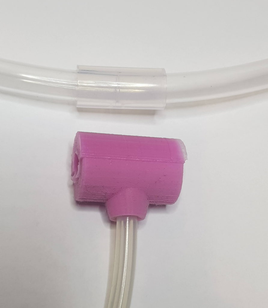
There’s one thing I didn’t mention yet, can you think what’s missing? How does the air flow from the main PPA tube through the vacuum flange? Do we drill a hole in the tube? Not a great ideas as keeping the tube intact is critical, because even tiny disruptions to the surface of the main tube could become a friction point that the ball would impact. Even the tiny plastic shavings from the drilling operation contaminate the main tube and disrupt the ball motion.
Instead, drill a 3 or 4mm diameter hole into one side of the tube joiner. Don’t drill right through it! Now, the custom vacuum flange will fit over the tube joiner, and the two tube ends will slide into the tube joiner. Tiny gaps between the main PPA tube endings in the joiner will allow air to escape the main tube.
Parts list
You can email me to order a kit containing the parts below, but please be aware stock is very limited and will not be replenished! The full list is published below for anyone who misses out on the limited stock.
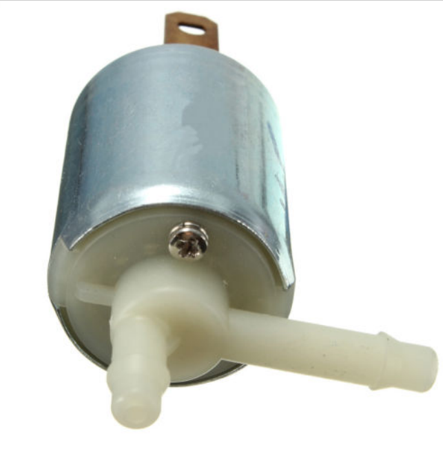
1 12V vacuum pump. There’s a number on the market, but only a few of them get down to 20kPa. Purchase from eBay. OD of ports around 4.5mm. Note: many suppliers have relatively fragile ports and care must be taken not to snap them off during transport, handling, or insertion of tubing.
1 12V pneumatic valve (OPTIONAL). Purchase from eBay.
1 length of 400mm or greater silicone tubing. Preferred dimensions are 6mm OD and 2.5mm ID.
1 T-piece to suit the silicone tubing. Purchase from eBay. OD of port is 5mm.
1 custom vacuum flange from Awesome.Tech OR 3d print a mold and use a small quantity of fast-set silicone molding mix eg. ‘pinkysil’ see video for usage
1 2N3904 MOSFET for controlling vacuum pump. This is the same MOSFET type as controls the Electromagnets.
1 2N3904 MOSFET for controlling pneumatic valve (OPTIONAL). This is the same MOSFET type as controls the Electromagnets.
2 300R resistors as R17 and R23 on the output board
1 MPXH6115AC6U Pressure Sensor from NXP, which can be purchased from Digikey. Note – there are many types of pressure sensors on the market and if you order another, ensure you research it well for compatibility.
1 100nF capacitor as C1 on the throttle board
1 47pF capacitor as C2 on the throttle board
1 51k resistor as R5 on the throttle boad
1N401 diodes for pump and solenoid, wired in reverse parallel to avoid MOSFET damage. Research flyback diodes if needed to understand their function.
2 2 pin terminals to act as connectors labelled PUMP and VALVE on the Output board. Pin spacing 5mm.
Instructions
Test vacuum pump (and pneumatic valve if used) with a 12V power supply.
If necessary, fabricate your own vacuum flange. 3d print files will be available on GitHub.
Install MOSFET(s) and associated components on PPA Output board
Install pressure sensor and associated components on throttle board. Note it is a surface mount device and the intrepid maker should practice soldering surface mount devices prior to attempting.
Hook up the parts as roughly shown in following photo, except that the flange must sit over the tube joiner.
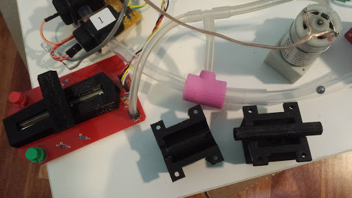
- fit the flange over the drilled tube end-piece
- fit the T-piece such that the pump draws air from the tubing to pressure sensor and flange
Adapt software to:
a) read vacuum pressure from sensor
b) display vacuum pressure on the screen
c) have one of the user interface buttons toggle the vacuum pump on/off
d) send vacuum pump state variable to vacuum pump MOSFET
e) send vacuum valve state variable to pneumatic valve MOSFET (OPTIONAL)
Possible extensions
- Research the drag equation
- Conduct a rolling-stop experiment by simply disabling the EM’s and seeing the curve over which the ball reduces velocity. By conducting this at atmospheric and various atmospheric pressures it should be possible to estimate the drag coefficient. Compare to literature.
- Improve the user interface to allow easy control of the vacuum pump.
This is wonderful. I’d like to order a set in case one is still available, including the 3D printed parts which would be the biggest problem for me.
Please let me know how to proceed and thank you for this!
Peter
Hi, just pinging again about how to buy the Vacuum kit, very keen on getting it and trying it out!
Hi Peter, re the 3d printed parts – you realise they’re only required if you want to fabricate the vacuum flange yourself? Making the flange is a lot of fun but I can just provide you a vacuum flange directly if you prefer – please let me know.
I’ve completed the list of electronic components