
Overview
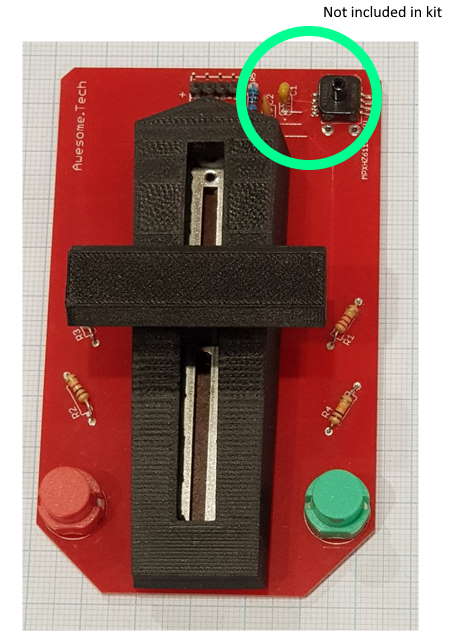
The throttle unit consists of a 3D printed assembly on top of a linear potentiometer (variable resistor), and supporting components on a printed circuit board.
Some additional functionality was not included in the Kickstarter – the PCB allows for some additional components to measure and report air pressure in the tube. Information to achieve this will be released in due course, for the moment ignore this in the photos please.
Instructions
| Component | Value | Identifier | Notes |
| R1 | 2k2 | Red, red, black, brown, brown. | Resistor divider network for switch and variable resistor |
| R2 | 1k | Brown, black, black, brown, brown. | Resistor divider network for switch and variable resistor |
| R3 | 3k9 | Orange, white, black, brown, brown. | Resistor divider network for switch and variable resistor |
| R4 | 10k | Brown, black, black, red, brown. | Resistor divider network for switch and variable resistor |
| 4 pin header connector | Connects Throttle to Output board | ||
| Slider potentiometer | 10k | Note polarity. The two pins of the potentiometer must be soldered to the end nearest the 4 pin header connector. |
Finally, solder the red and green coloured switches in the orientation shown in the main photo.
Mechanical assembly
Slide the potentiometer movement to the centre of its travel.
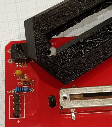
Insert the M3 nylon nut into the small cavity in the inner top of the throttle shell. A sharp instrument such as a small screwdriver may be required to clear the area of the 3d printed material prior to inserting the nut. Insert the M3 nylon bolt through the PCB from underneath. See photo below.
Now position the shell in place over the potentiometer and tighten the nylon bolt into the retaining nut by tightening with a screwdriver from underneath.
Push the throttle handle down onto the potentiometer movement. Note there is a slight angle on one face of the throttle handle – this is designed to face towards to the forward position of the throttle.
Resistors 1,2,4 didn’t match colours here, due to 4vs5 band colouring.
2k2 resistor is red,red,red,gold.
1k is brown, black, red
3k9 resistor matched 5 bands
10k brown, black, orange, gold
Thanks Phil, that’s right some resistors are 4 band, some are 5.
Hi, do you have an update on the components to measure and report air pressure in the tube? I would like to implement this capability in my set-up. if you have a parts-list and instructions for it, that would be amazing. Thank you! Peter
Hi Peter,
hope you’re doing well. I’ll put together a parts list and instructions, please give me a week or so.
Regards, Dan
Great, thank you!
Hi Peter!
Please find new page https://awesome.tech/vacuum-for-your-ppa/
Could I get your feedback please? Still needs a few final details on minor components, anything else?
Cheers
Dan