
K40 Middlemen board
To help out connecting a K40 laser machine to a Super Gerbil Controller board, we have created a simple K40 middlemen board.
It is a basic board where we connect the screw terminal connections on the Super Gerbil to the propriety connectors so it becomes just a straight plugin from the K40 via the K40 middlemen board.
Additional axis enables K40 motorised bed height adjustment
Although our Mini Gerbil controller for K40 is selling like hot cakes, some customers need richer features, including motorised bed height adjustment. This is helpful for cutting thicker materials, or for precision management of the laser’s focal point. The new Super Gerbil controller can easily drive a bed height adjustment motor (as well as the usual X, Y and laser PWM signals), and the new ‘middleman connector’ allows you to easily connect the K40 to the Super Gerbil.
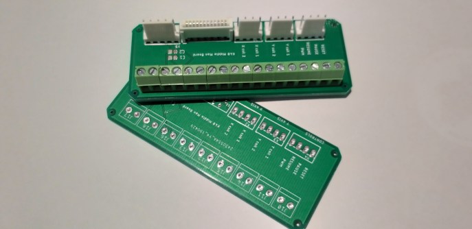
The K40 middlemen board schematic and board are very simple and straight forward see the pictures below.
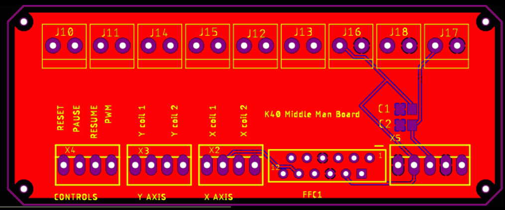


The ribbon cable will just fit into the FFC connector, ensure the connector lips and receptacle contacts are matching. If you don’t have a ribbon cable than use the 5 pin connector header next to the FFC connector on the right for the limit switch connection and use the X-axis motor connector for the X-axis motor plug. The non-ribbon K40 versions do have their X axis and limit switches spread over two separate connectors which are also available on the middlemen board. If you have a ribbon cable that of course you leave the X-axis header and limit switch header empty.
As you see the K40 middlemen board is very simple and straight forward and we will make this little PCB board available in our web store shortly and a very small price.
Wiring Up the K40
The wiring of the SG to the K40 are just a few steps:
- Wire up all the power rails on the Super Gerbil (SG) to Middlemen board
- Connect limits switches X,Y and Z from SG to Middlemen board
- Optional – add control buttons to SG
- Connect Motor axis X,Y from SG to Middlemen board and add a Z axis directly to the SG screw terminals
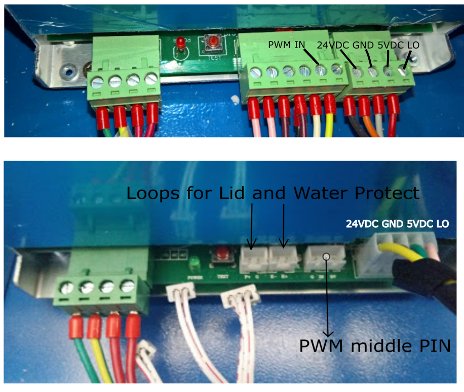
- Connect the Direction MOSFET output to the LO screw terminal on the Laser Power supply
- Connect the PWM wire from the PWM driver to the IN screw terminal on the Laser Power supply
Note: There is no need to switch on the Fire switch on the K40.
Note: the Opto coupler can be used instead of the PWM driver, however the zero is not rest free hence S=0 still has laser output. With the PWM driver, you have zero output at S=0.
An external power supply might be required since the 24V DC can only deliver 1-2 Amps. Make sure you don’t use a transformer less or switched power supply since the ground terminal could be on the wrong polarity with the ground terminal of the laser power supply.


Enjoy!
Thanks guys,
You saved me a few hours work with your handy little K40 converter board.
Thanks Richard, always glad to help! Cheers Paul
Will this be for sale soon please?
Hi the boards have been ordered but the corona virus does impact the production and delivery. We hope it will be in this month (March) and will keep an eye on it. Thanks, Paul
Hi Neil,
the Middleman board is currently in production, but given Chinese factories are understaffed currently it’s too early to provide a date these will be in stock. Please check back in a month.
Regards,
Dan
Hi guys,
I purchased two middleman boards and have been trying to get them to work.
I eventually worked out the the ribbon cable connectors are different to the one on your pictures above and due to the way the new connector fits the ribbon cable is reversed.
to fix this i would need to desolder the ribbon cable connector and put it on the bottom side of board. This is not something that I would be confident about trying.
Could you let me know what you can do to help
Thanks Jeff