
T2laser testing
Quote from tprothma on November 3, 2018, 5:10 amHi Paul, I really appreciate the offer. I'm happy and a little confused though. I though USBasp was built into the base board. If there is a piece of hardware I can buy from Amazon that would be perfectly fine with me. Could you point me to one you think would work.
Would this one work? Sparkfun Pocket AVR Programmer
https://www.amazon.com/gp/product/B004G54E9I/ref=ox_sc_act_title_1?smid=AFBMYHRQ9KU5H&psc=1
Thanks,
Tim
Hi Paul, I really appreciate the offer. I'm happy and a little confused though. I though USBasp was built into the base board. If there is a piece of hardware I can buy from Amazon that would be perfectly fine with me. Could you point me to one you think would work.
Would this one work? Sparkfun Pocket AVR Programmer
https://www.amazon.com/gp/product/B004G54E9I/ref=ox_sc_act_title_1?smid=AFBMYHRQ9KU5H&psc=1
Thanks,
Tim
Quote from Paul on November 3, 2018, 5:52 amSparkfun is a very reputable company so I am pretty sure it works. I got mine from Jaycar in Australia and a few from eBay. The Chinese ones are using a USB clone bridge which is not digitally signed hence Win10 stops you. The zadigexe program is a way around it and I suspect that Microsoft has stopped that loophole as well. Let me know how you go otherwise I will flash a board for you. Cheers Paul
Sparkfun is a very reputable company so I am pretty sure it works. I got mine from Jaycar in Australia and a few from eBay. The Chinese ones are using a USB clone bridge which is not digitally signed hence Win10 stops you. The zadigexe program is a way around it and I suspect that Microsoft has stopped that loophole as well. Let me know how you go otherwise I will flash a board for you. Cheers Paul
Quote from tprothma on November 3, 2018, 11:30 amGreat... Can you post a picture of one plugged in. I don't see a 10 pin header on the base board.
BTW, my shield has the green solder mask. Does that represent an earlier revision of the shield or just an earlier build of the latest design?
Thanks!
Great... Can you post a picture of one plugged in. I don't see a 10 pin header on the base board.
BTW, my shield has the green solder mask. Does that represent an earlier revision of the shield or just an earlier build of the latest design?
Thanks!
Quote from tprothma on November 3, 2018, 9:13 pmI think this one will work to adapt the 10 pin on USBasp to the 6pin ISP header on the Arduino.
https://www.amazon.com/gp/product/B00FHHYJ7G/ref=ox_sc_act_title_1?smid=AO2R8RP2MLB3M&psc=1
Tim
I think this one will work to adapt the 10 pin on USBasp to the 6pin ISP header on the Arduino.
https://www.amazon.com/gp/product/B00FHHYJ7G/ref=ox_sc_act_title_1?smid=AO2R8RP2MLB3M&psc=1
Tim
Quote from Paul on November 3, 2018, 9:27 pmHi, I was about to take a photo but you already located the adapter. Normally they are supplied with the programmer. Also a little flat cable is included. So maybe check with the amazon seller.
Cheers, Paul
Hi, I was about to take a photo but you already located the adapter. Normally they are supplied with the programmer. Also a little flat cable is included. So maybe check with the amazon seller.
Cheers, Paul
Quote from tprothma on November 3, 2018, 9:54 pmOh, in addition to the 10 pin on the ribbon cable that connects to the USBasp, it looks like there are 2 more headers on the ribbon cable- one is 10pin and the other with slightly muxed pins is a 6pin. So it looks like it is in fact included (very subtle).
Thanks!
Oh, in addition to the 10 pin on the ribbon cable that connects to the USBasp, it looks like there are 2 more headers on the ribbon cable- one is 10pin and the other with slightly muxed pins is a 6pin. So it looks like it is in fact included (very subtle).
Thanks!
Quote from tprothma on December 3, 2018, 4:30 pmok, everything is working great with the new board.
I found that you can in debug mode for T2 or in any command line, you can eliminate the need to invert the image and flip sign of Y axis.
Simply home $h, this brings the head to to the upper left, then use a rapid movement G0 Y-220 to bring the head to bottom left. Then use G92X0Y0 and it will now consider this offset basically setting a local coordinate system. Then all the remaining G0 and G01 commands that result in movement with positive Y. This does not require setting a G54 type workposition command which writes to EEPROM which has a limited number of writes due to endurance limit of the silicon.
What are you setting for vRef and Imax for the drivers?
ok, everything is working great with the new board.
I found that you can in debug mode for T2 or in any command line, you can eliminate the need to invert the image and flip sign of Y axis.
Simply home $h, this brings the head to to the upper left, then use a rapid movement G0 Y-220 to bring the head to bottom left. Then use G92X0Y0 and it will now consider this offset basically setting a local coordinate system. Then all the remaining G0 and G01 commands that result in movement with positive Y. This does not require setting a G54 type workposition command which writes to EEPROM which has a limited number of writes due to endurance limit of the silicon.
What are you setting for vRef and Imax for the drivers?
Quote from Paul on December 3, 2018, 7:38 pmGreat work and glad that you got your set up working. The Imax per driver is 2A but the power supply can only deliver 1 Amp in total and has not buildin overload protection (sigh). So you need to set the current to 0.45A max.
If you want to set the current limit to 0.45 A and you have a board with 68 mΩ sense resistors, you would set VREF to 243 mV which corresponds to a quarter turn of the smd driver pot.
Cheers, Paul
Great work and glad that you got your set up working. The Imax per driver is 2A but the power supply can only deliver 1 Amp in total and has not buildin overload protection (sigh). So you need to set the current to 0.45A max.
If you want to set the current limit to 0.45 A and you have a board with 68 mΩ sense resistors, you would set VREF to 243 mV which corresponds to a quarter turn of the smd driver pot.
Cheers, Paul
Quote from tprothma on December 4, 2018, 2:41 pmoh, ok. That confirms my hunch as I think the drivers were previously set to 1.2V and things were not working properly, but when I set them to 0.8V which seemed to straightened things out. I don't know how to confirm the value of the sense resistors (not familiar with the different driver types), so I can only say that what I had for Vref.
On the TMC2130's and TMC2100's the Vref = Imax (works out to be 1:1)
https://learn.watterott.com/silentstepstick/faq/I see you're offering the 2100's as part of super gerbil and it looks like you sourced them from the same place I did (blue soldermask).
BTW, Vref is very sensitive. If you measure Vref as you turn the pot and you'll see what I mean. Frankly, I would not rely on eyeballing its position. It's easy enough to measure between gnd and any part of the metal on the pot for most pololu (like A4988), and measure between gnd and the probe pin closest to the headers for the TMC drivers.
Different drivers have different scaling between Vref and Imax. Do you have datasheets for the ones with the red soldermask?
Thanks!
oh, ok. That confirms my hunch as I think the drivers were previously set to 1.2V and things were not working properly, but when I set them to 0.8V which seemed to straightened things out. I don't know how to confirm the value of the sense resistors (not familiar with the different driver types), so I can only say that what I had for Vref.
On the TMC2130's and TMC2100's the Vref = Imax (works out to be 1:1)
https://learn.watterott.com/silentstepstick/faq/
I see you're offering the 2100's as part of super gerbil and it looks like you sourced them from the same place I did (blue soldermask).
BTW, Vref is very sensitive. If you measure Vref as you turn the pot and you'll see what I mean. Frankly, I would not rely on eyeballing its position. It's easy enough to measure between gnd and any part of the metal on the pot for most pololu (like A4988), and measure between gnd and the probe pin closest to the headers for the TMC drivers.
Different drivers have different scaling between Vref and Imax. Do you have datasheets for the ones with the red soldermask?
Thanks!
Uploaded files: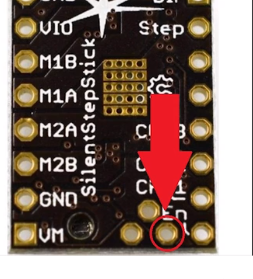
Quote from Paul on December 4, 2018, 6:37 pmHi, the A4988's are basically all clones of the Pololu steppers and the datasheets are here: https://www.pololu.com/product/1182
They all have the 68mOhm current sense resistor nowadays unless you have a very old batch of step sticks. It's very hard to see which one because these Chinese clones don't have values printed on them. Probably the only way to get around it, is to replace the sense resistor a with a new 68mOhm resistor and measure the voltage and compare the pot setting.
The TMC's is a different story. Basically the TMC2130 is the direct drop in equivalent for the A4988. Indeed the current setting is very difficult since the chip has logic on board to counter any overshoot and or high current demands. So you fighting against the logic in the chip! In practice this means just very small tiny adjustments can be made otherwise you lost track whether it was a good or bad correction. Smile!
Hi, the A4988's are basically all clones of the Pololu steppers and the datasheets are here: https://www.pololu.com/product/1182
They all have the 68mOhm current sense resistor nowadays unless you have a very old batch of step sticks. It's very hard to see which one because these Chinese clones don't have values printed on them. Probably the only way to get around it, is to replace the sense resistor a with a new 68mOhm resistor and measure the voltage and compare the pot setting.
The TMC's is a different story. Basically the TMC2130 is the direct drop in equivalent for the A4988. Indeed the current setting is very difficult since the chip has logic on board to counter any overshoot and or high current demands. So you fighting against the logic in the chip! In practice this means just very small tiny adjustments can be made otherwise you lost track whether it was a good or bad correction. Smile!
Quote from Paul on December 4, 2018, 6:38 pmSorry no datasheets yet but Google is our friend (setup a Google alert is my best tip)
Sorry no datasheets yet but Google is our friend (setup a Google alert is my best tip)
Quote from tprothma on December 5, 2018, 3:38 amok, great. This really good info. BTW, I noticed the sensitivity of the POT on the A4988's and I forgot to mention the motor needs to be disconnected while doing the adjustment (of course). I have not used the TMC2130's yet on your board, because I did not want to introduce any variables at this time.
ok, great. This really good info. BTW, I noticed the sensitivity of the POT on the A4988's and I forgot to mention the motor needs to be disconnected while doing the adjustment (of course). I have not used the TMC2130's yet on your board, because I did not want to introduce any variables at this time.