
No PWM Control, non standard PSU
Quote from George Dryburgh on September 30, 2023, 6:00 amHowdy folks,
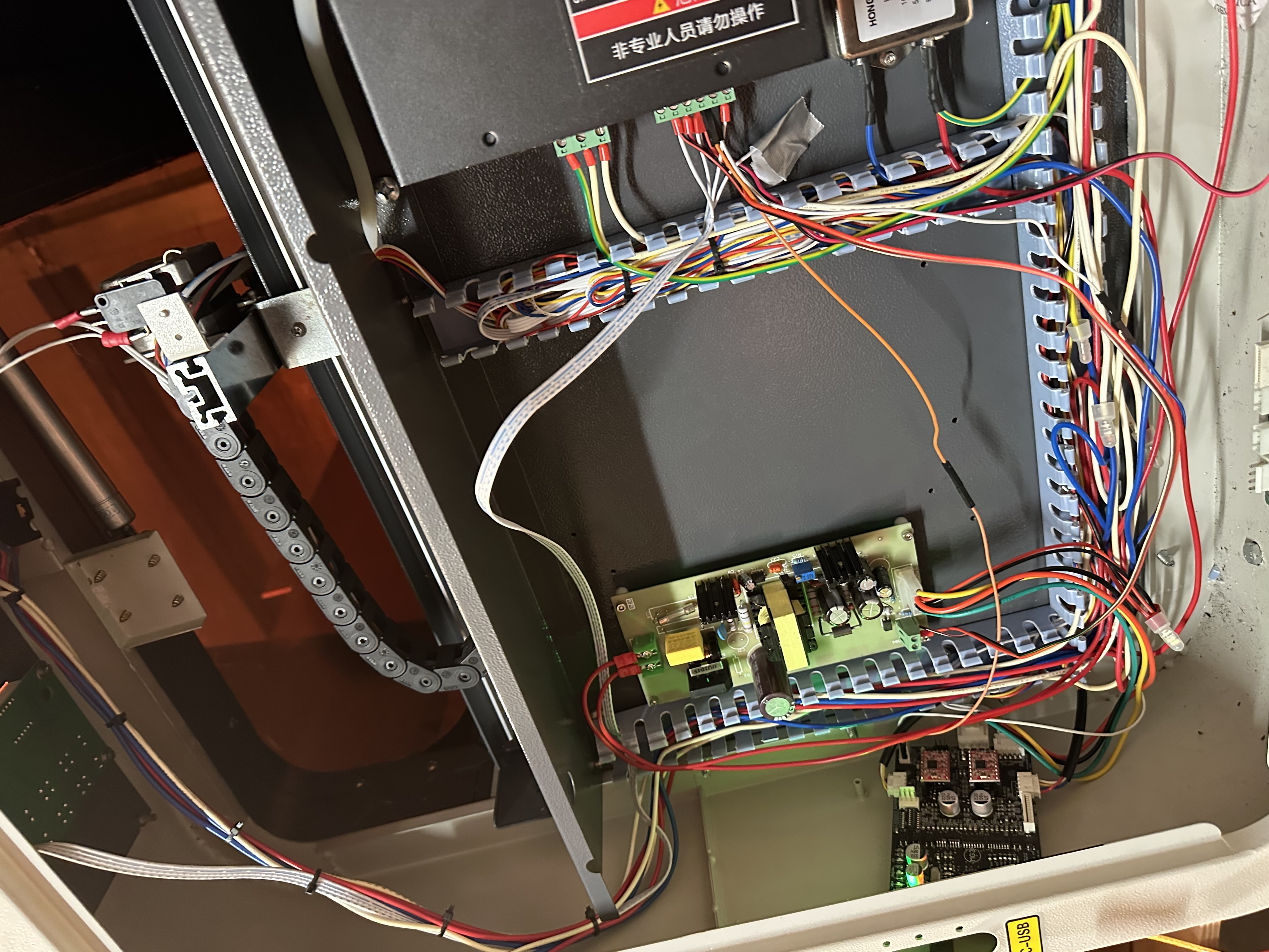
I purchased a Chinese made 50W CO2 4060 second-hand. It’s the big grey box on wheels if anyone knows what that means.
I instantly swapped out the stock M2 Nano controller for the MG3 so I could use Lightburn but the wiring is more complex than on a K40 it seems.
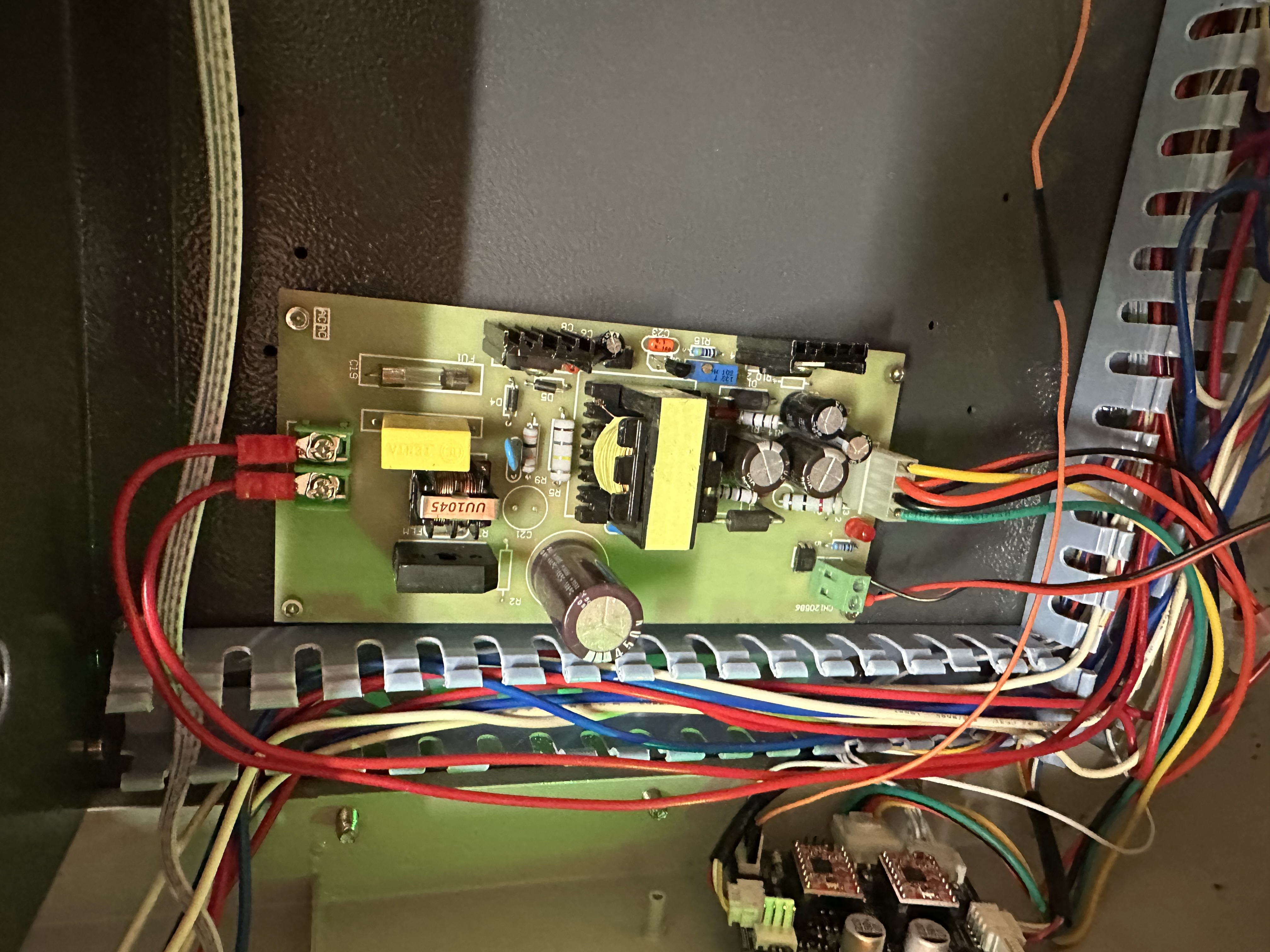
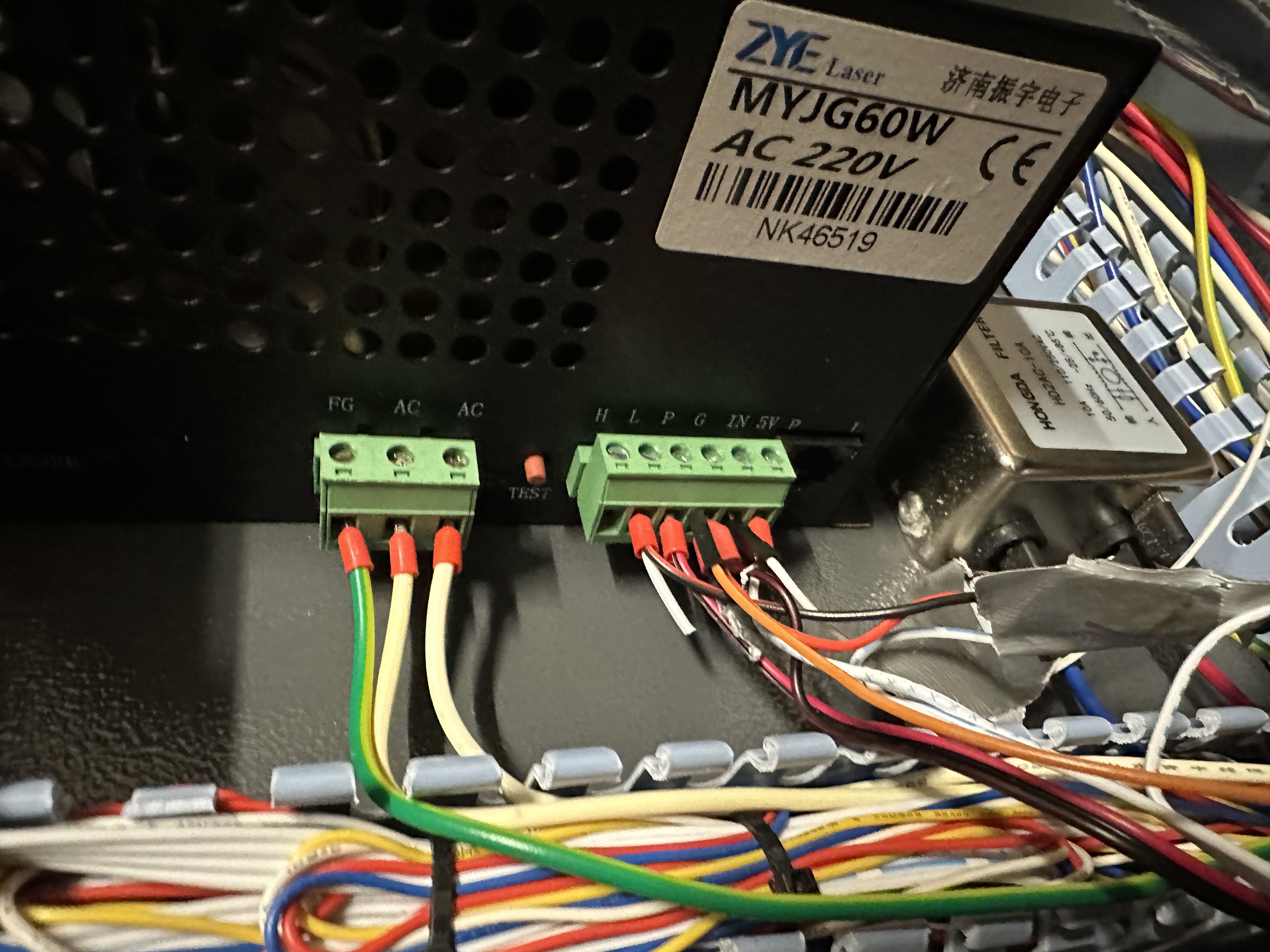
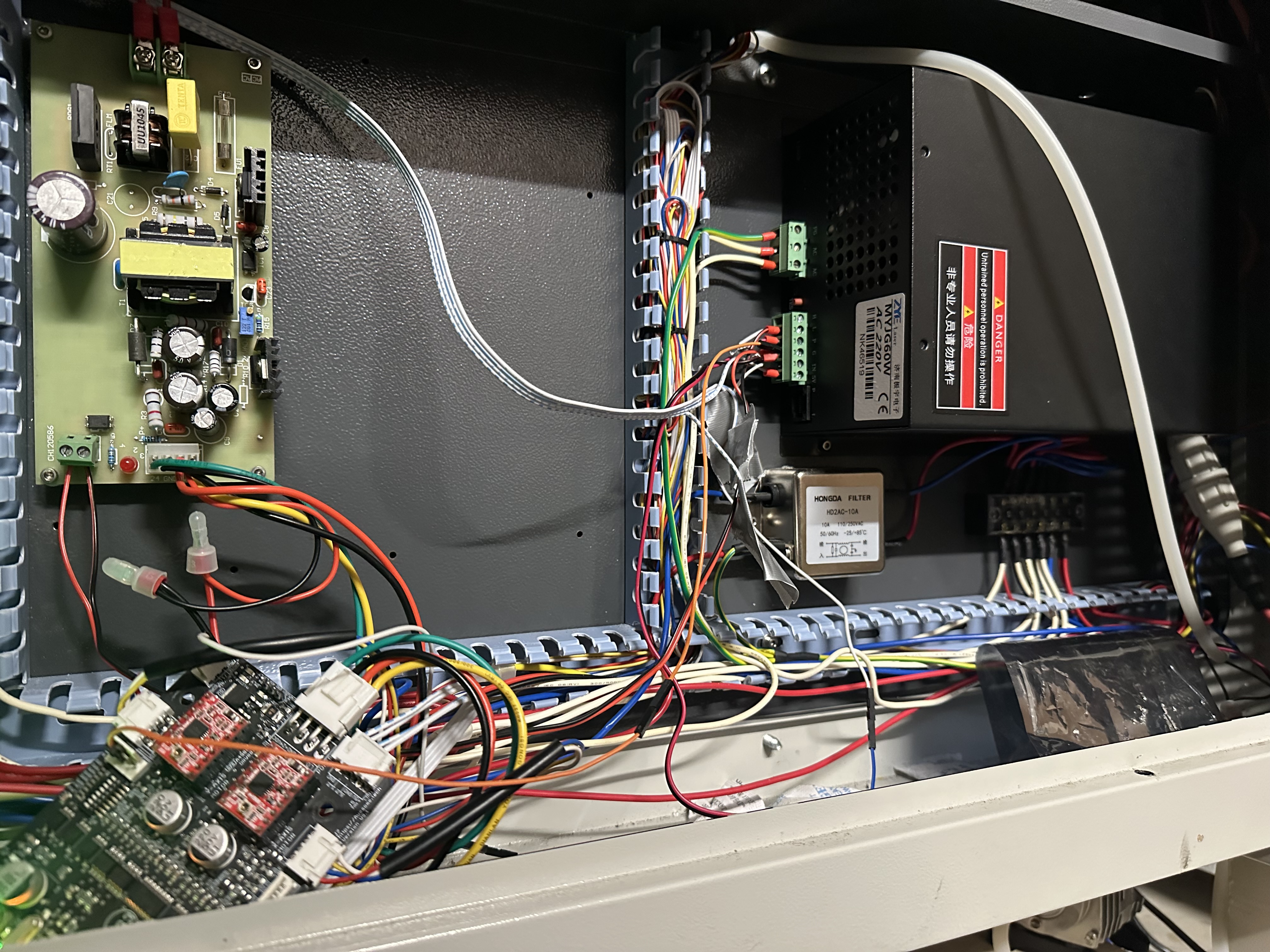
There is an extra board that appears to be a power supply separate from the LPS that is connected to the LPS mains via a relay. The L and G connect to this board at the bottom and the “big 4 pin connector” comes from this to plug into the MG3.
So far I have managed to get the laser on off control correct but at this stage I have no PWM control.
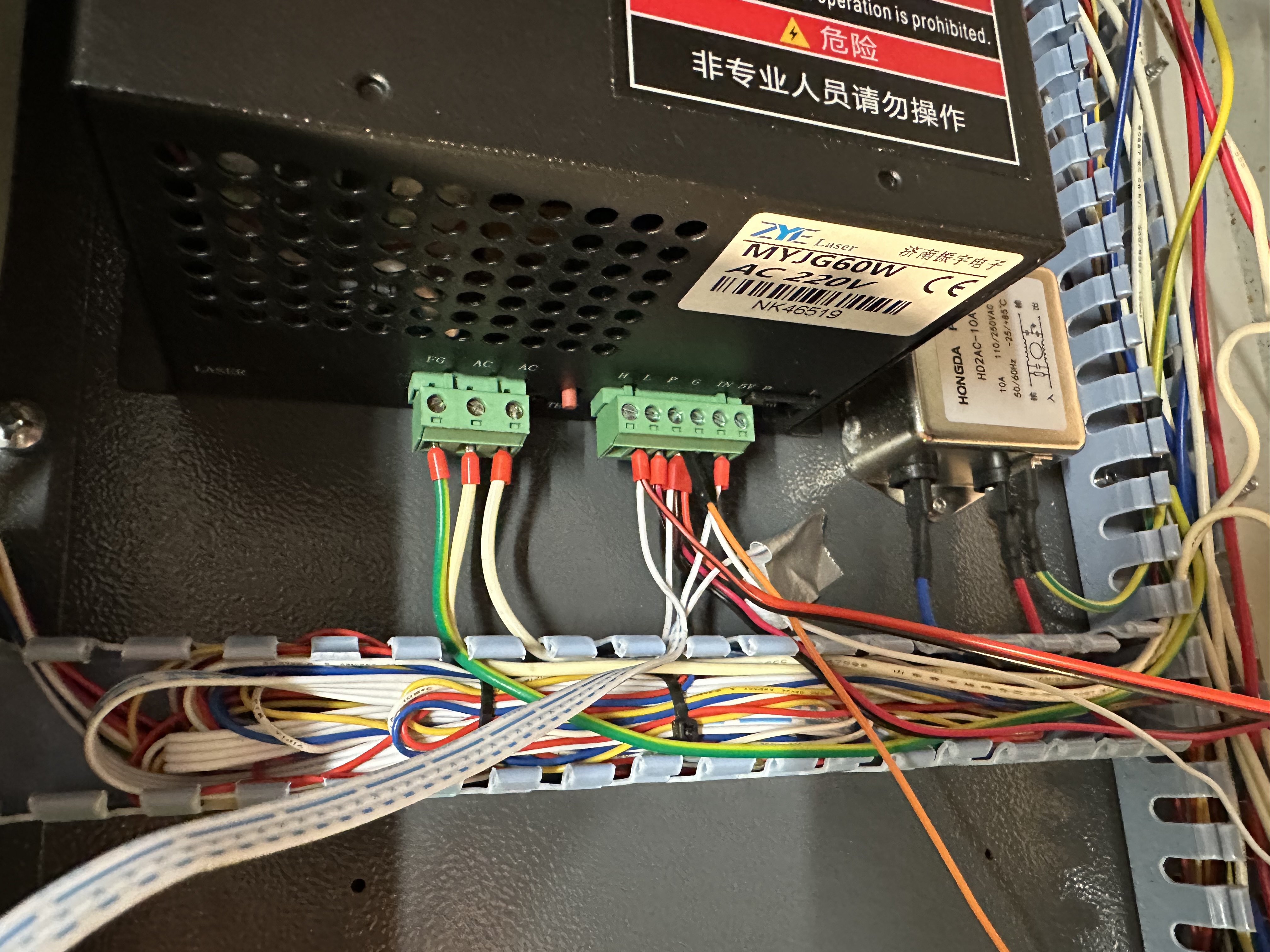
My wiring is as follows:
H - connected to nothing
L - connected to the Power Supply Board mentioned earlier
P - connected to a water flow sensor in the back
G - connected to the big power supply board next to the L. Also connected to the J2 common ground pin on the MG3 (this solved an issue where the laser was remaining on during travel moves.
IN - Connected to the PWM pin on the MG3 as instructed
5V - was connected to the top panel but currently goes nowhere.
My $32 value is correct, I am definitely in Laser mode.
Is anyone able to help please?
Howdy folks,
I purchased a Chinese made 50W CO2 4060 second-hand. It’s the big grey box on wheels if anyone knows what that means.
I instantly swapped out the stock M2 Nano controller for the MG3 so I could use Lightburn but the wiring is more complex than on a K40 it seems.
There is an extra board that appears to be a power supply separate from the LPS that is connected to the LPS mains via a relay. The L and G connect to this board at the bottom and the “big 4 pin connector” comes from this to plug into the MG3.
So far I have managed to get the laser on off control correct but at this stage I have no PWM control.
My wiring is as follows:
H - connected to nothing
L - connected to the Power Supply Board mentioned earlier
P - connected to a water flow sensor in the back
G - connected to the big power supply board next to the L. Also connected to the J2 common ground pin on the MG3 (this solved an issue where the laser was remaining on during travel moves.
IN - Connected to the PWM pin on the MG3 as instructed
5V - was connected to the top panel but currently goes nowhere.
My $32 value is correct, I am definitely in Laser mode.
Is anyone able to help please?
Uploaded files:
Quote from dancolwp1974 on September 30, 2023, 8:16 pmHi George,
I can definitely help, we've got lots of these up and running.
Ok, some principles are:
1 Be very focussed on safety. If you don't know what you're doing, you'll need some local help. I can see red wires labelled 'AC' on one of your photos, so that's an example of something that you'd need to ensure was 100% safe. Always turn off power before working.
2 The general principle is to strip out everything that's not needed. You don't want old circuit boards and wiring there to confuse and be problematic. So you need to
3 You'll need to take very clear photos. For example, your photo of the LPS power supply seems to show the PWM wire going into the Ground, clearly that won't work. Maybe as you say it is connected to IN, but from the way I'm looking at the photo, it's hard to tell. So could you please re-take any photos that aren't representative of the actual connections.
Ok, with that out of the way, please remove the board shown in 'IMG_4682.jpg' It's the one with the two red AC wires. So you'll need to trace them back to where they come from and disconnect them from source.
The MG3 should be connected to the LPS something like shown in this image
https://awesome.tech/installing-mg-type1/ (note the MG is the prior version, but easy to see the differences).
Note that the 5V LPS connection must be connected to the MG4 on the big four pin connector.
Cheers
Dan
Hi George,
I can definitely help, we've got lots of these up and running.
Ok, some principles are:
1 Be very focussed on safety. If you don't know what you're doing, you'll need some local help. I can see red wires labelled 'AC' on one of your photos, so that's an example of something that you'd need to ensure was 100% safe. Always turn off power before working.
2 The general principle is to strip out everything that's not needed. You don't want old circuit boards and wiring there to confuse and be problematic. So you need to
3 You'll need to take very clear photos. For example, your photo of the LPS power supply seems to show the PWM wire going into the Ground, clearly that won't work. Maybe as you say it is connected to IN, but from the way I'm looking at the photo, it's hard to tell. So could you please re-take any photos that aren't representative of the actual connections.
Ok, with that out of the way, please remove the board shown in 'IMG_4682.jpg' It's the one with the two red AC wires. So you'll need to trace them back to where they come from and disconnect them from source.
The MG3 should be connected to the LPS something like shown in this image
https://awesome.tech/installing-mg-type1/ (note the MG is the prior version, but easy to see the differences).
Note that the 5V LPS connection must be connected to the MG4 on the big four pin connector.
Cheers
Dan
Quote from George Dryburgh on October 1, 2023, 10:33 amHi Dan,
Thanks for jumping in.
So I just need to clarify once again that this is not a K40. I have no doubt that it’s similar but it is using a 60w LPS with a different layout.
I do not believe that I can exclude the xtra board as I think it is actually a component of the LPS itself. It had the 24V 4 pin connector, not the black box itself. Hopefully the photos show this. It is connected via a relay to the AC out on the black box.
The PWM out on the MG3 is most definitely connected to the IN on the LPS. As I mentioned in my previous post, I have an extra wire coming from the G to the J2 common ground pin on the MG3. This solved a previous issue I was having where the laser was always on even during travel moves.
Hopefully this clears things up as to where I’m at
Hi Dan,
Thanks for jumping in.
So I just need to clarify once again that this is not a K40. I have no doubt that it’s similar but it is using a 60w LPS with a different layout.
I do not believe that I can exclude the xtra board as I think it is actually a component of the LPS itself. It had the 24V 4 pin connector, not the black box itself. Hopefully the photos show this. It is connected via a relay to the AC out on the black box.
The PWM out on the MG3 is most definitely connected to the IN on the LPS. As I mentioned in my previous post, I have an extra wire coming from the G to the J2 common ground pin on the MG3. This solved a previous issue I was having where the laser was always on even during travel moves.
Hopefully this clears things up as to where I’m at
Uploaded files: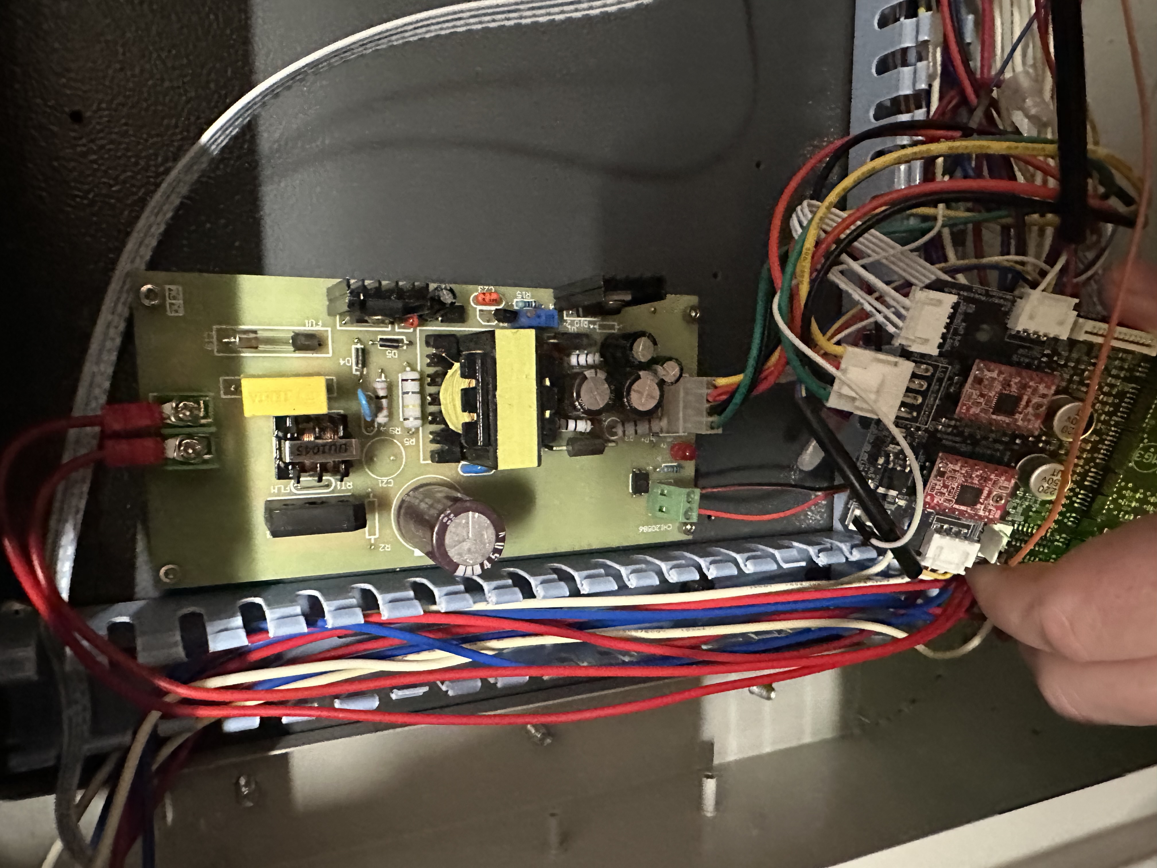
Quote from George Dryburgh on October 1, 2023, 10:58 amI've tried to illustrate the attached photo to show you how it's hooked up atm.
Hopefully this adds more clarity.
I'm wondering, do I need to disconnect the yellow L from the 4 pin 24v connector and just run it straight from the L on the power supply?
I've tried to illustrate the attached photo to show you how it's hooked up atm.
Hopefully this adds more clarity.
I'm wondering, do I need to disconnect the yellow L from the 4 pin 24v connector and just run it straight from the L on the power supply?
Uploaded files: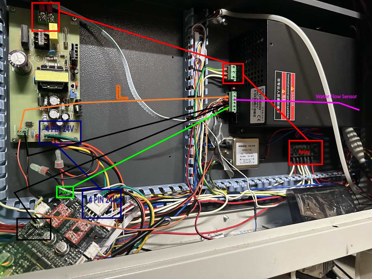
Quote from dancolwp1974 on October 2, 2023, 10:35 pmHi George,
Thanks for the update.
Noted it's not a K40.
You correctly note that the legacy PCB is a 24V power supply (for the stepper motors). I know this is not what you want to hear, but it's more trouble than it's worth. Strongly recommend purchasing a modern and reliable 24V supply for the steppers and scrapping this old PCB. This will clean up all your wiring and simplify everything. As well as making the installation easier, you'll also benefit from higher reliability and easier fault-finding down the track.
In sticking with that theme, I recommend bypassing or scrapping the legacy PCB wherever possible. So, yes, please wire the yellow LO wire from the MG3 straight to the L of the Laser Power supply.
Thanks
Dan
Hi George,
Thanks for the update.
Noted it's not a K40.
You correctly note that the legacy PCB is a 24V power supply (for the stepper motors). I know this is not what you want to hear, but it's more trouble than it's worth. Strongly recommend purchasing a modern and reliable 24V supply for the steppers and scrapping this old PCB. This will clean up all your wiring and simplify everything. As well as making the installation easier, you'll also benefit from higher reliability and easier fault-finding down the track.
In sticking with that theme, I recommend bypassing or scrapping the legacy PCB wherever possible. So, yes, please wire the yellow LO wire from the MG3 straight to the L of the Laser Power supply.
Thanks
Dan
Quote from George Dryburgh on October 4, 2023, 7:29 pmHi Dan,
Thanks for this.
No worries, I’ll look into replacing the stepper PSU ASAP. Any recommendations? A Meanwell or something?
For now, I’ve wired the LO on the MG3 direct to the L on the LPS. This has given me SOME PWM control.
At %100 in Lightburn, I’m now getting far less power from the laser than I was before and there is now a high pitched noise coming from the LPS which I understand to be part of the PWM in action.
I’ve attempted to raise the S Max values (within safe bounds) to see if I was just under powering the laser but that doesn’t seem to be the issue either.
Do I also need to connect the 5V from the LPS to the 5V on the MG3 now?
Hi Dan,
Thanks for this.
No worries, I’ll look into replacing the stepper PSU ASAP. Any recommendations? A Meanwell or something?
For now, I’ve wired the LO on the MG3 direct to the L on the LPS. This has given me SOME PWM control.
At %100 in Lightburn, I’m now getting far less power from the laser than I was before and there is now a high pitched noise coming from the LPS which I understand to be part of the PWM in action.
I’ve attempted to raise the S Max values (within safe bounds) to see if I was just under powering the laser but that doesn’t seem to be the issue either.
Do I also need to connect the 5V from the LPS to the 5V on the MG3 now?
Quote from dancolwp1974 on October 5, 2023, 10:03 pmHi George,
Yes, a meanwell would be fine.
re LO wiring to L on the LPS - good
I think the S Max value works differently to what you think it does, but in any case, yes, you should be connecting the 5V and GND of the MG3 to the LPS. Just like I wrote before, you need to move in the direction of these direct connections for everything to 'just work'
A high pitched noise from the LPS is not a promising sound. Not normal and not welcome. I'm unsure how old your laser is, but this likely indicates that your LPS may be on the way out. This could also be related to getting limited PWM range. You didn't specify if we know that the system works fine with the old controller.
A general suggestion, can you please move towards diagrams of wiring? The photos are very busy and would hate there to be any misunderstanding about connections as you wrap up the converstion. Hand drawn connection diagrams are fine.
Cheers
Dan
Hi George,
Yes, a meanwell would be fine.
re LO wiring to L on the LPS - good
I think the S Max value works differently to what you think it does, but in any case, yes, you should be connecting the 5V and GND of the MG3 to the LPS. Just like I wrote before, you need to move in the direction of these direct connections for everything to 'just work'
A high pitched noise from the LPS is not a promising sound. Not normal and not welcome. I'm unsure how old your laser is, but this likely indicates that your LPS may be on the way out. This could also be related to getting limited PWM range. You didn't specify if we know that the system works fine with the old controller.
A general suggestion, can you please move towards diagrams of wiring? The photos are very busy and would hate there to be any misunderstanding about connections as you wrap up the converstion. Hand drawn connection diagrams are fine.
Cheers
Dan