
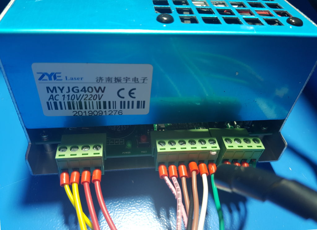
If your K40 power supply is the one shown below, you’re in the right place! You can tell by looking at the number and spacing of the green terminal blocks.
[NOTE: photos shown are illustrative – your wire colors may differ. The wiring connections is what matters.]
Step 0 – Turn off your K40 at the wall
Step 1 – Choose your mounting option
| Mini Gerbil Mounting Options | Instructions |
| Install alongside the Nano controller using the adhsesive PCB standoffs – fast and convenient for an initial installation | Push the PCB standoffs through the MG’s corner holes until the small tab engages. Rotate the standoff untill the tab faces the nearest corner (enabling easy removal later). Wipe mounting plate clean. Remove adhesive backing and push onto mounting plate. |
| Re-use the existing Nano mounting place – great for a long term solution | With a permanent marker, label the white plugs going into the Nano controller. Photograph the Nano controller including labelled plugs before unplugging the cables from the Nano. Unbolt the K40’s existing controller mounting plate and remove the Nano. Screw the Mini Gerbil to the Nano’s mounting place. Plug the labelled cables as described in instructions |
Step 2 – Review installation diagram and plug in
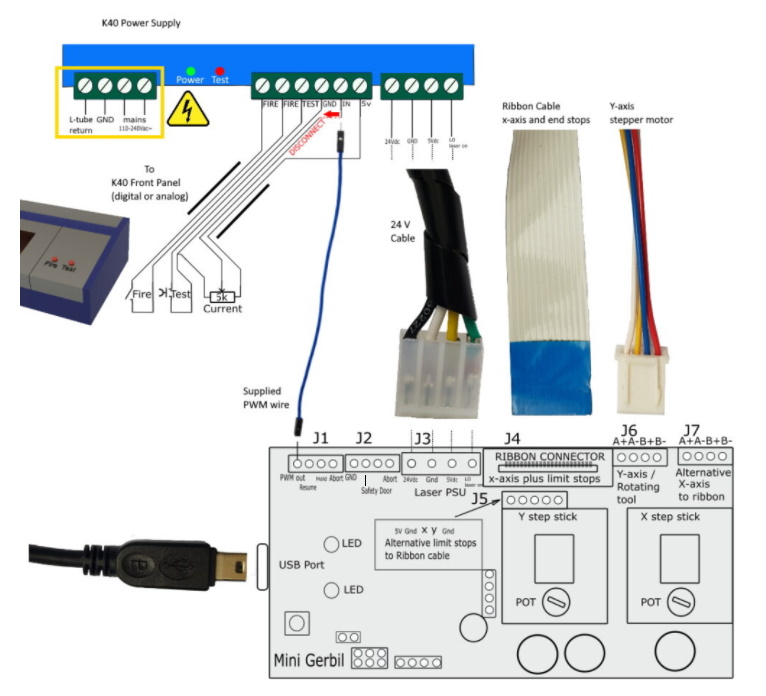
The following table guides you through connecting according to the diagram above:
| Item/area | Instructions | Explanation |
| YELLOW BOX | DANGER – DO NOT TOUCH. DO NOT CHANGE. | Existing High Voltage connections |
| BLACK wires | do not change | Existing front panel connections |
| Existing 24V Cable with large 4 wire connector | Remove from Nano and plug into Mini Gerbil J3. Fit connector key towards the centre of the board and lock in | Provides 24V DC for the stepper motors and 5V DC power for the Mini Gerbil’s processing. |
| Existing Ribbon cable | Remove from Nano and plug into J4. Ensure the ribbon cable’s metal contacts touch the socket’s metal contacts. If there’s no ribbon cable, plug your equivalent limit switch connector to J5, and your equivalent X axis motor connector to J7. | The ribbon connector supplies the X direction stepper motor, and both limit switches. |
| Existing small 4 wire cable with connector | Remove from Nano and plug into Mini Gerbil J6 | Y axis stepper motor connector |
| Existing wire connecting to IN connector (red dashed) | Unscrew the existing wire from IN connector shown in red dash and insulate with electrical tape. Now plug in the supplied wire between the IN connector and Mini Gerbil J1 PWM. | Laser strength is now controlled digitally by your Mini Gerbil and software, not the K40’s front panel. |
| Additional features | Where they exist, connect your laser’s additional features including Fault, Safety Door and Abort to this connector. | 2 is optional, as these features aren’t available on all K40’s. |
Return to Installing the Mini Gerbil