
Different K40 with different wiring
Quote from matteo oddone on February 6, 2024, 10:50 pmHi ...several probs down here ...cause i'm a rookie and my k40 is totally different from what i was able to see in the tutorials ..i'm also an electronics enthusiast ..trained with pcb and soldering but with a simple to replicate project ...here i'm in front of something too big for me
hope you will help me
i've tried to follow these instruction but with no luck
the gerbill showed is different and also my wiring and connctros are different (at my eyes)
https://awesome.tech/installing-mini-gerbil-on-the-k40-type2/
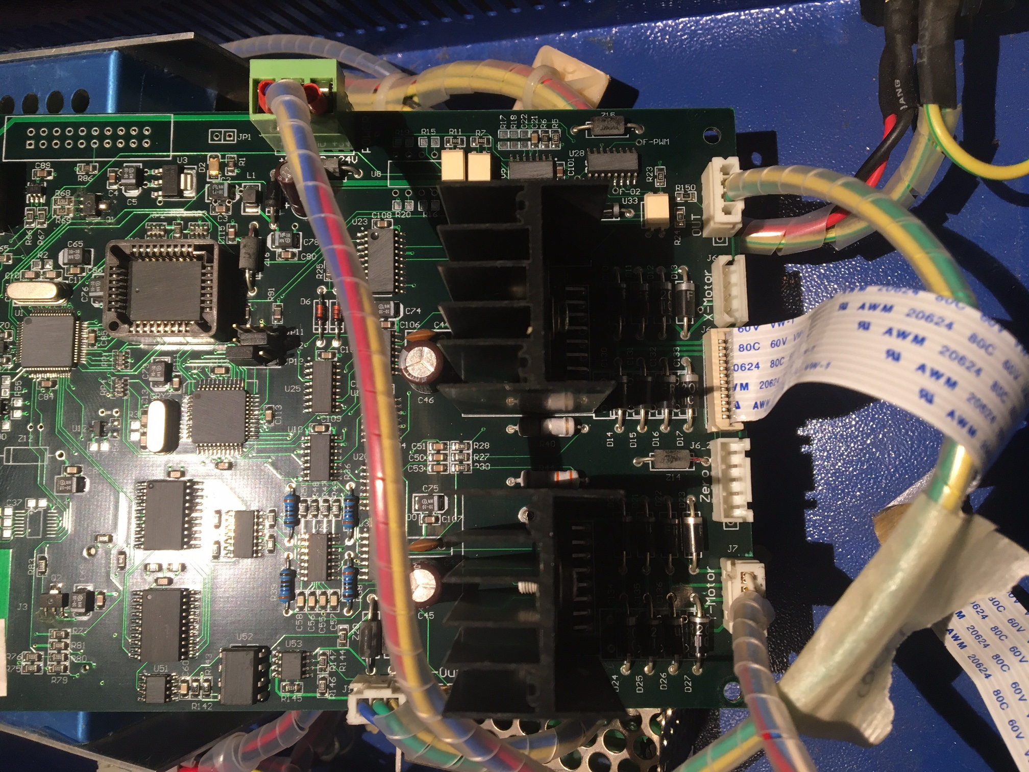
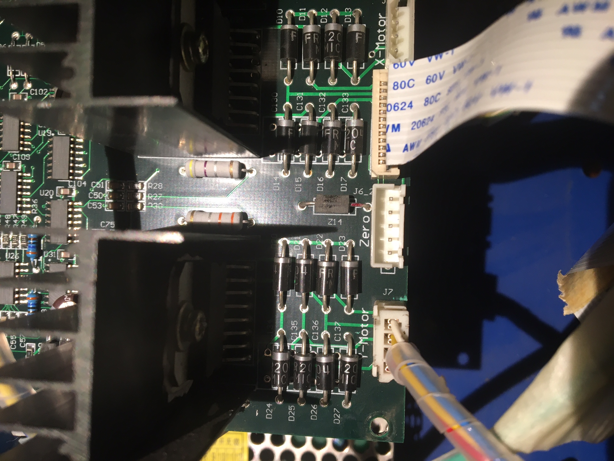
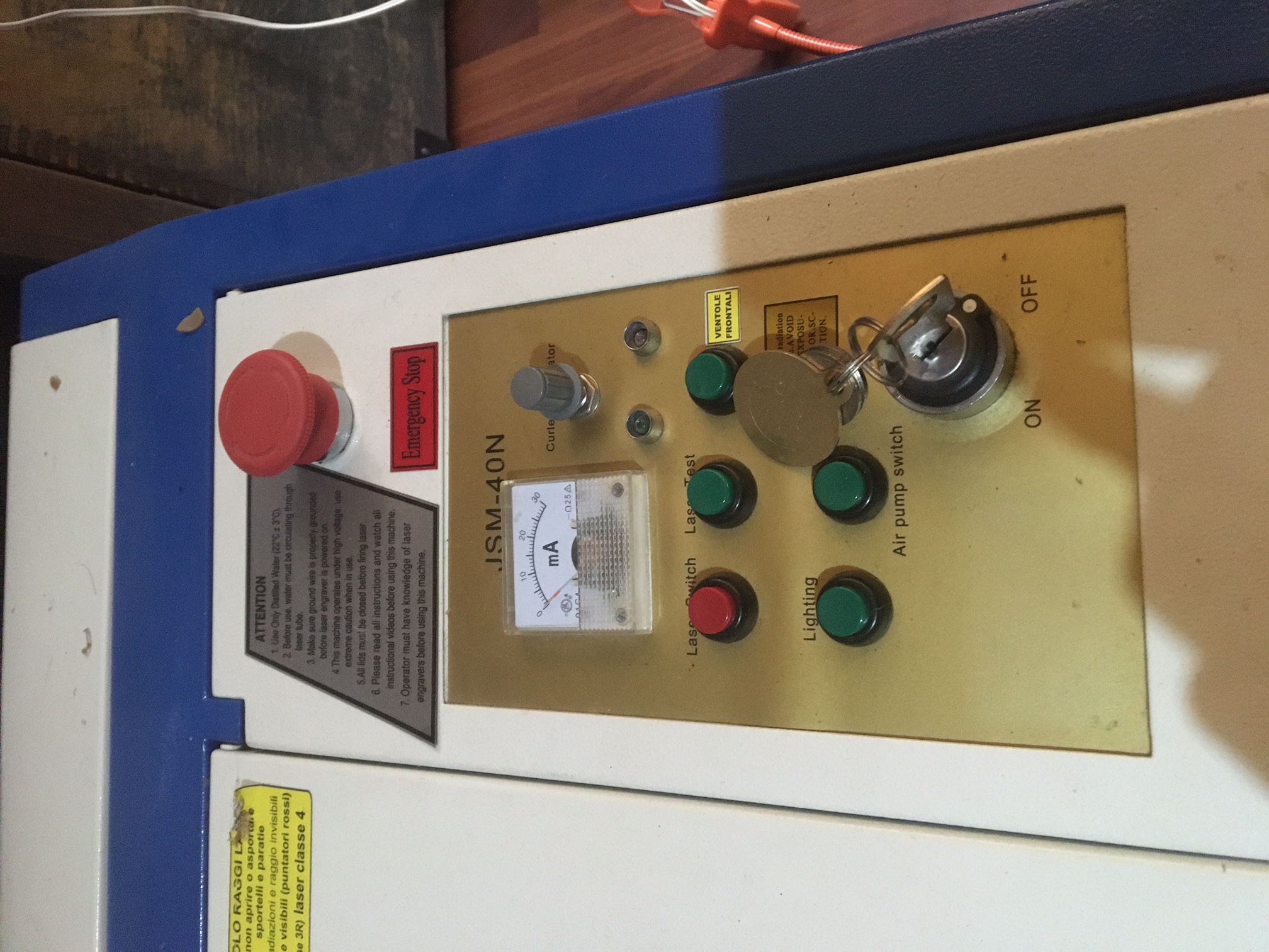
so i'll attach the photos of my old controller and the power supply installed
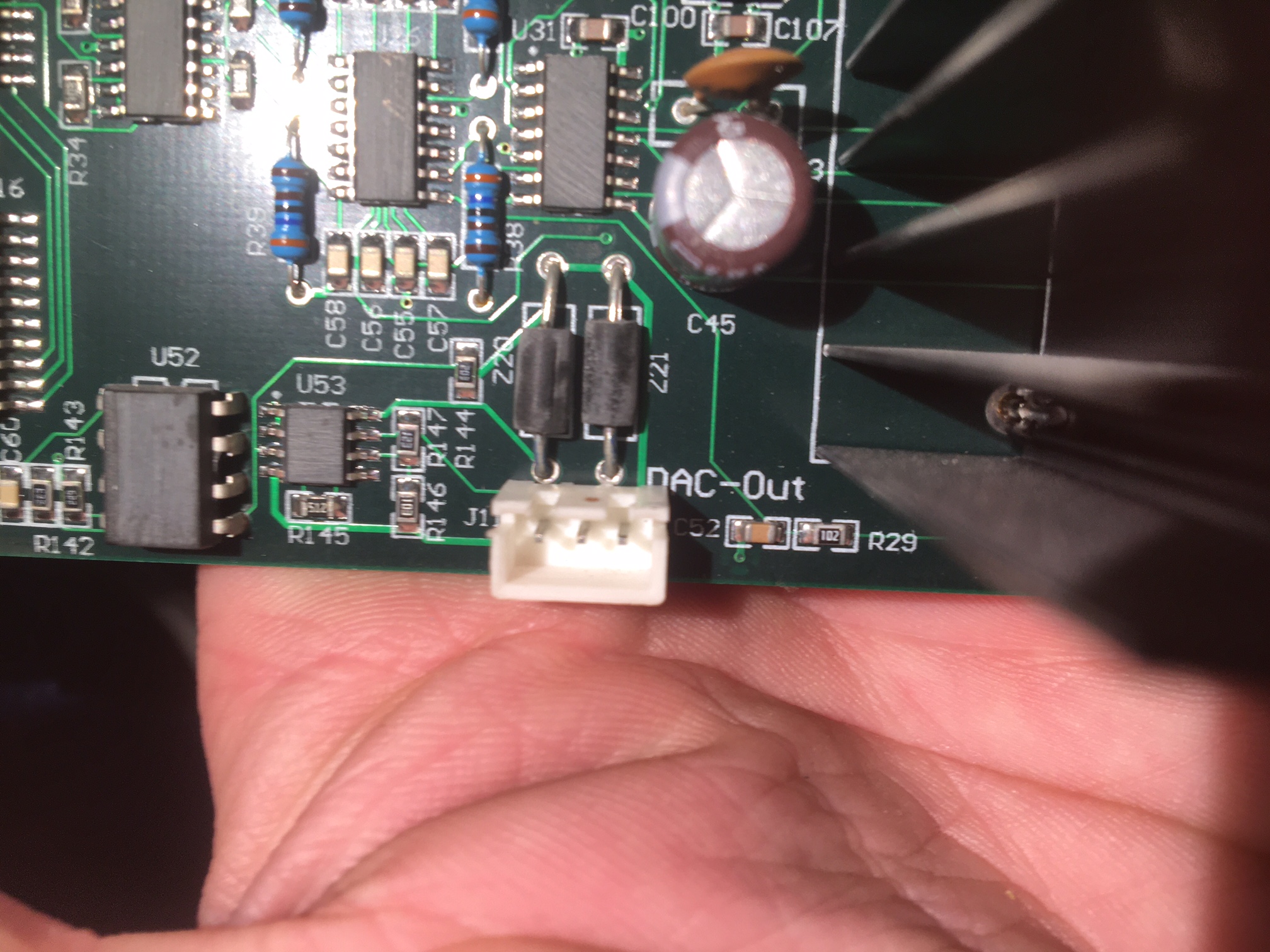
i've got DAC OUT (?!?) with 3 pins
power to the old board is 3 pins
OUT of the old board is 4 pins
probably for you is easy ...for me is a bit thrilling 🙂
link me to a topic ...if it was already solved ...i was unable to find a solution in the forum ..but i didn't open all the topics
Hi ...several probs down here ...cause i'm a rookie and my k40 is totally different from what i was able to see in the tutorials ..i'm also an electronics enthusiast ..trained with pcb and soldering but with a simple to replicate project ...here i'm in front of something too big for me
hope you will help me
i've tried to follow these instruction but with no luck
the gerbill showed is different and also my wiring and connctros are different (at my eyes)
so i'll attach the photos of my old controller and the power supply installed
i've got DAC OUT (?!?) with 3 pins
power to the old board is 3 pins
OUT of the old board is 4 pins
probably for you is easy ...for me is a bit thrilling 🙂
link me to a topic ...if it was already solved ...i was unable to find a solution in the forum ..but i didn't open all the topics
Uploaded files:
Quote from Paul on February 8, 2024, 11:46 amHi Matteo,
It seems you have a very new Chinese controller board but the laser power supply (PSU) is still the same. That's good news because you should be able to use the MG with the PSU.
X-motor - goes to the x motor connector on the MG (Mini Gerbil)
Ribbon cable (endstops and Y motor) - goes to the ribbon connector on the MG
P+ - is the protect loop. Just bridge this connection. Used in the scenario of a water protect or laser lid switch.
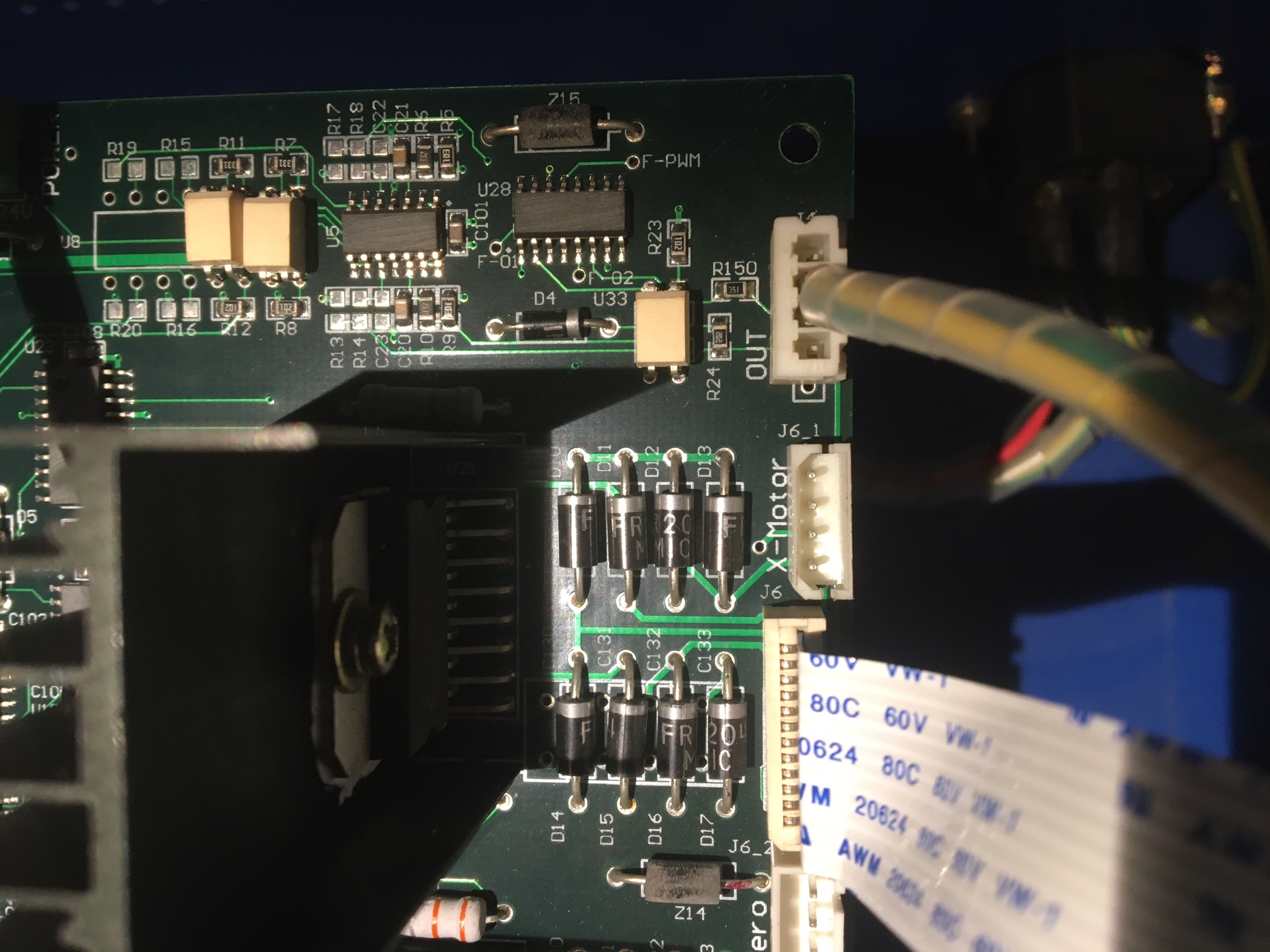
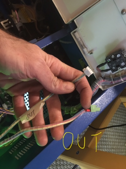
OUT and DAC Out - follow the leads and take photo's where the originate from so I can help you further.
One should be the laser power pot or digital panel and the other should be a laser enable switch (LO pin on the PSU power connector) .
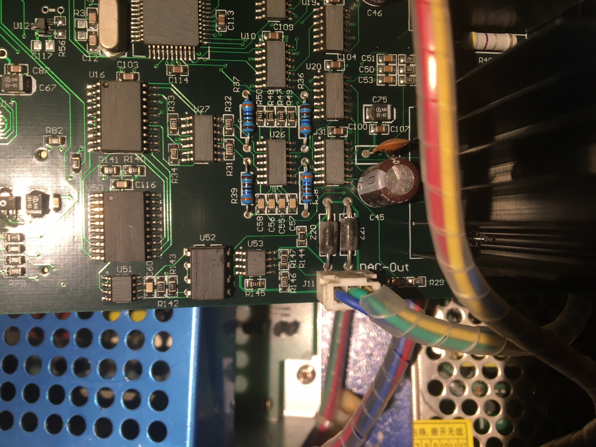
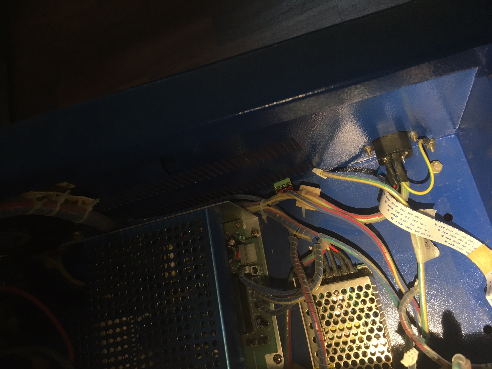
24VDC, GND, 5VDC, LO are on the PSU connector (your last photo) - that should connect to the MG. Question is how much power does the laser unit require? Since the last photo shows and empty power (4pins) , I wonder if an external power supply is used for powering the motors? If you can have a look and take a photo of an external power supply then that would help to understand what the current configuration is. That would help to understand how to move to the use of the PSU with empty power connector or whether we need to use the external power supply and add some wiring. At this moment, that is unclear to me.
Thanks Paul
Hi Matteo,
It seems you have a very new Chinese controller board but the laser power supply (PSU) is still the same. That's good news because you should be able to use the MG with the PSU.
X-motor - goes to the x motor connector on the MG (Mini Gerbil)
Ribbon cable (endstops and Y motor) - goes to the ribbon connector on the MG
P+ - is the protect loop. Just bridge this connection. Used in the scenario of a water protect or laser lid switch.
OUT and DAC Out - follow the leads and take photo's where the originate from so I can help you further.
One should be the laser power pot or digital panel and the other should be a laser enable switch (LO pin on the PSU power connector) .
24VDC, GND, 5VDC, LO are on the PSU connector (your last photo) - that should connect to the MG. Question is how much power does the laser unit require? Since the last photo shows and empty power (4pins) , I wonder if an external power supply is used for powering the motors? If you can have a look and take a photo of an external power supply then that would help to understand what the current configuration is. That would help to understand how to move to the use of the PSU with empty power connector or whether we need to use the external power supply and add some wiring. At this moment, that is unclear to me.
Thanks Paul
Quote from matteo oddone on February 9, 2024, 10:34 pmoh wow ...thank you so much ....i'll work on the k40 on monday ...i'll post the request photos ...now i fell more confident ....thanks again 🙂
oh wow ...thank you so much ....i'll work on the k40 on monday ...i'll post the request photos ...now i fell more confident ....thanks again 🙂
Quote from matteo oddone on February 15, 2024, 9:44 pma bit late ...but here 🙂
a bit late ...but here 🙂
Uploaded files:
Quote from Paul on February 19, 2024, 10:19 amHi Matteo,
From what I see is that you have an additional power supply. The reason for that is, the board in the K40 seems a very new design which probably does not work well because of the laser tube noise. The good news is that you don't need that additional power supply. You can remove the wiring and just use the Laser power supply (5V and 24Vdc) with the LO laser on signal. These are 4 wires from the laser supply to the MG board. The plug you need is an MTA156 plug, don't solder the wires directly but use a plug. MTA156 is the series which stands for TE connectivity with a pitch of 156 or 0.156" (3.96mm)
https://www.digikey.com.au/en/products/detail/te-connectivity-amp-connectors/3-640429-4/696764
The potmeter can be just omitted since the MG controls the power via software (e.g. lightburn with G code commands e.g. S100 give 10% power). Just plug in the motor axis plug and Y axis/endstop ribbon as per instructions. Make sure you bridge the P+ and GND connection (water or loop protect) otherwise the laser won't fire.
Let me know how you go.
Hi Matteo,
From what I see is that you have an additional power supply. The reason for that is, the board in the K40 seems a very new design which probably does not work well because of the laser tube noise. The good news is that you don't need that additional power supply. You can remove the wiring and just use the Laser power supply (5V and 24Vdc) with the LO laser on signal. These are 4 wires from the laser supply to the MG board. The plug you need is an MTA156 plug, don't solder the wires directly but use a plug. MTA156 is the series which stands for TE connectivity with a pitch of 156 or 0.156" (3.96mm)
https://www.digikey.com.au/en/products/detail/te-connectivity-amp-connectors/3-640429-4/696764
The potmeter can be just omitted since the MG controls the power via software (e.g. lightburn with G code commands e.g. S100 give 10% power). Just plug in the motor axis plug and Y axis/endstop ribbon as per instructions. Make sure you bridge the P+ and GND connection (water or loop protect) otherwise the laser won't fire.
Let me know how you go.
Uploaded files: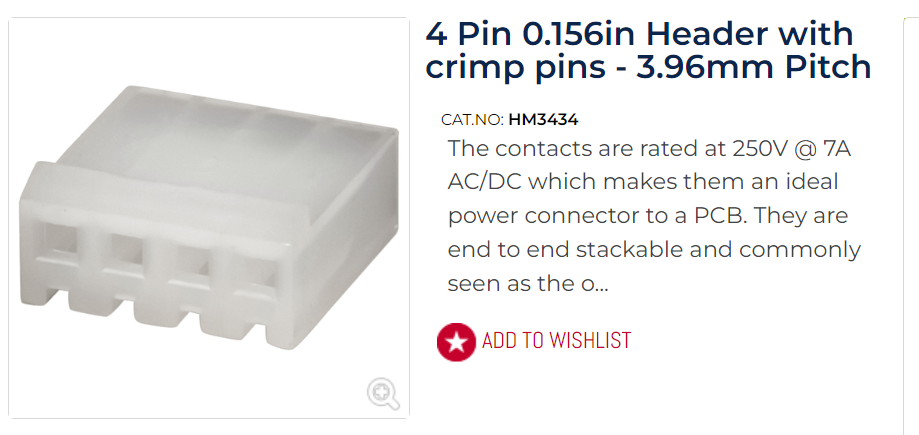
Quote from matteo oddone on February 29, 2024, 7:17 pmoh wow ...sorry for being late ....busy with probs
i've ordered the connector ...and then i'll work on it
hope i don't need your help anymore 🙂
thank you so much
oh wow ...sorry for being late ....busy with probs
i've ordered the connector ...and then i'll work on it
hope i don't need your help anymore 🙂
thank you so much
Quote from matteo oddone on March 13, 2025, 8:44 amMake sure you bridge the P+ and GND connection (water or loop protect) otherwise the laser won't fire.
Let me know how you go.
hello Paul
sounds strange but i'm back on the project just now
i've unplugged all the cable from the second psu
but i didn't understand P+ and ground bridge
the board work
light burn recognized it
the head moves
but the laser won't fire
pls help me again 🙂
Make sure you bridge the P+ and GND connection (water or loop protect) otherwise the laser won't fire.
Let me know how you go.
hello Paul
sounds strange but i'm back on the project just now
i've unplugged all the cable from the second psu
but i didn't understand P+ and ground bridge
the board work
light burn recognized it
the head moves
but the laser won't fire
pls help me again 🙂
Quote from Paul on March 13, 2025, 9:21 amThe P+ and Ground is just a jumper between the two terminals. Normally this is a switch on the control panel or on the lid. It's meant as a safety measure, if an unauthorized person or child turns on the machine, it can't fire or when someone opens the lid while the machine is operating, the laser will turn off to protect the eyes. On most k40's it's not implemented as a switch but people just bridge them (jumper wire between two terminals).
Hope this helps, Cheers Paul
The P+ and Ground is just a jumper between the two terminals. Normally this is a switch on the control panel or on the lid. It's meant as a safety measure, if an unauthorized person or child turns on the machine, it can't fire or when someone opens the lid while the machine is operating, the laser will turn off to protect the eyes. On most k40's it's not implemented as a switch but people just bridge them (jumper wire between two terminals).
Hope this helps, Cheers Paul
Quote from matteo oddone on March 13, 2025, 5:48 pmbefore writing i've triple checked the inside wirings
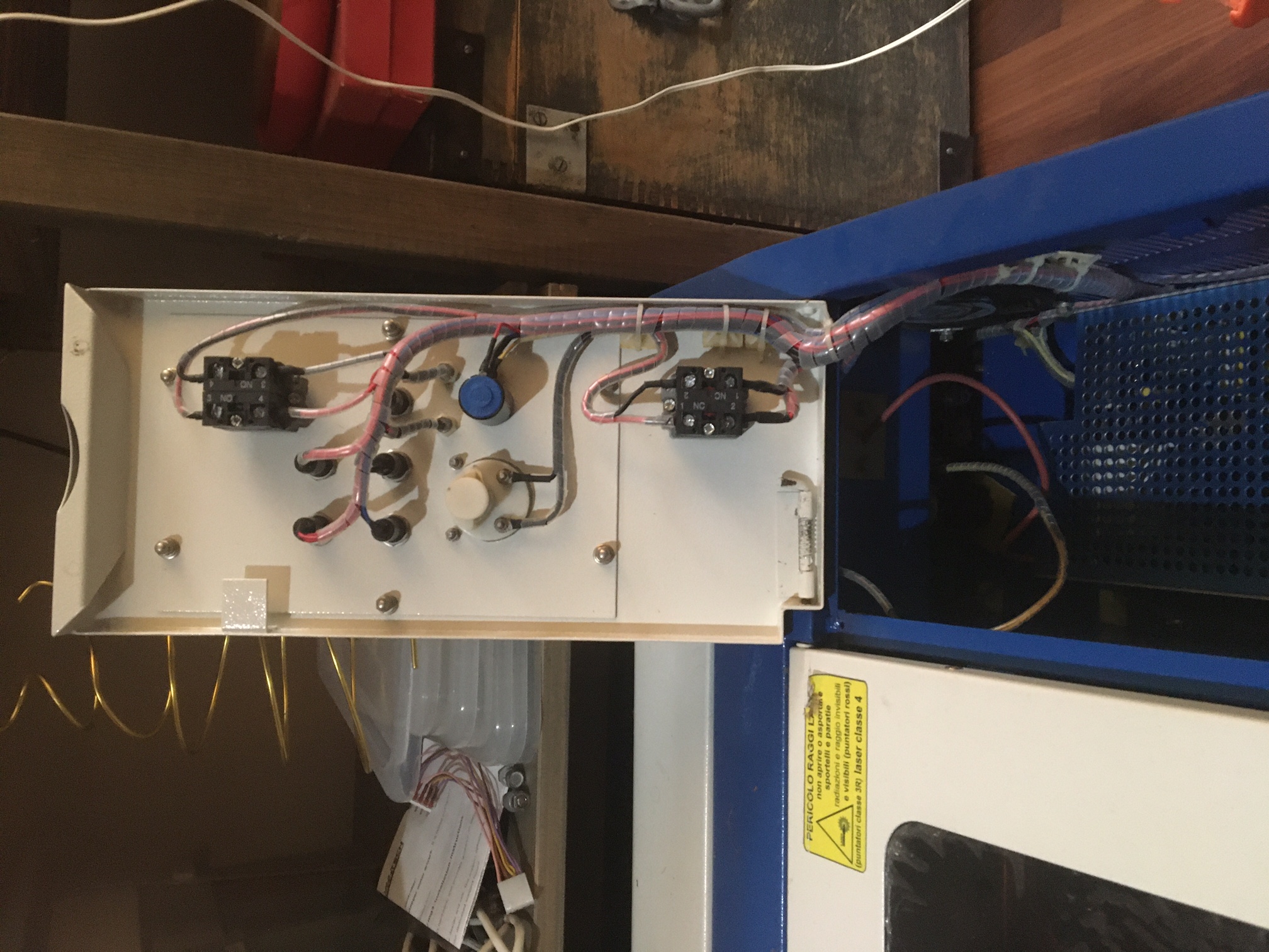
the lid switchs
i0ve niticed that now that ive unplugged the secondary psu ..the fansì and the lights don't work anymore
should i replug it ?
on the main lid (the one that covers the head and laser main plate ..there a magnetic switch ,,,and probably something else as security check
and any other idea to find the P+ ground bridge ?
wich wire should i try to follow ?
before writing i've triple checked the inside wirings
the lid switchs
i0ve niticed that now that ive unplugged the secondary psu ..the fansì and the lights don't work anymore
should i replug it ?
on the main lid (the one that covers the head and laser main plate ..there a magnetic switch ,,,and probably something else as security check
and any other idea to find the P+ ground bridge ?
wich wire should i try to follow ?
Quote from Paul on March 13, 2025, 7:45 pmYes you need the second PSU because that's delivering power to the steppers. The MG3 board needs both 5V DC and 24VDC.
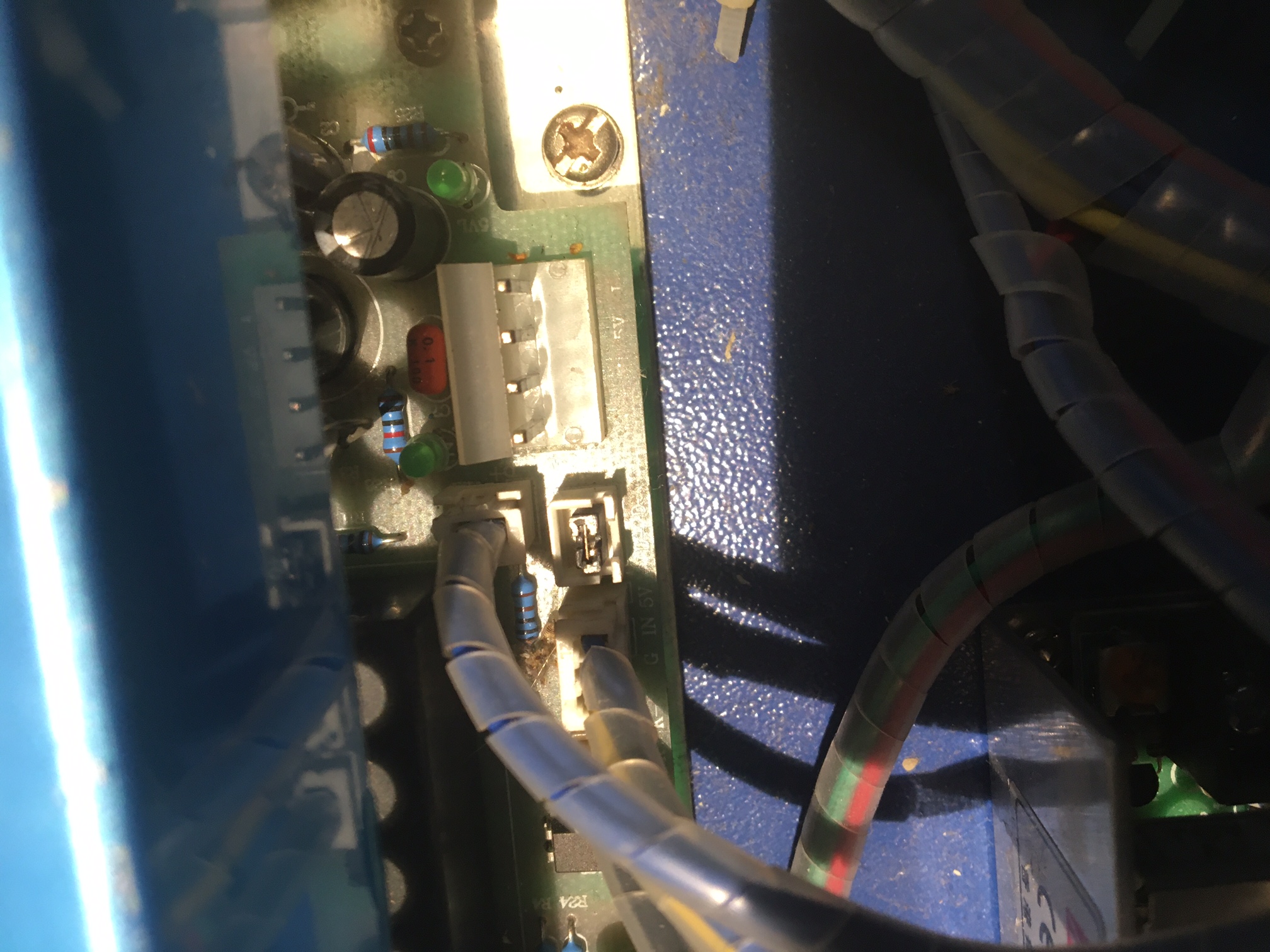
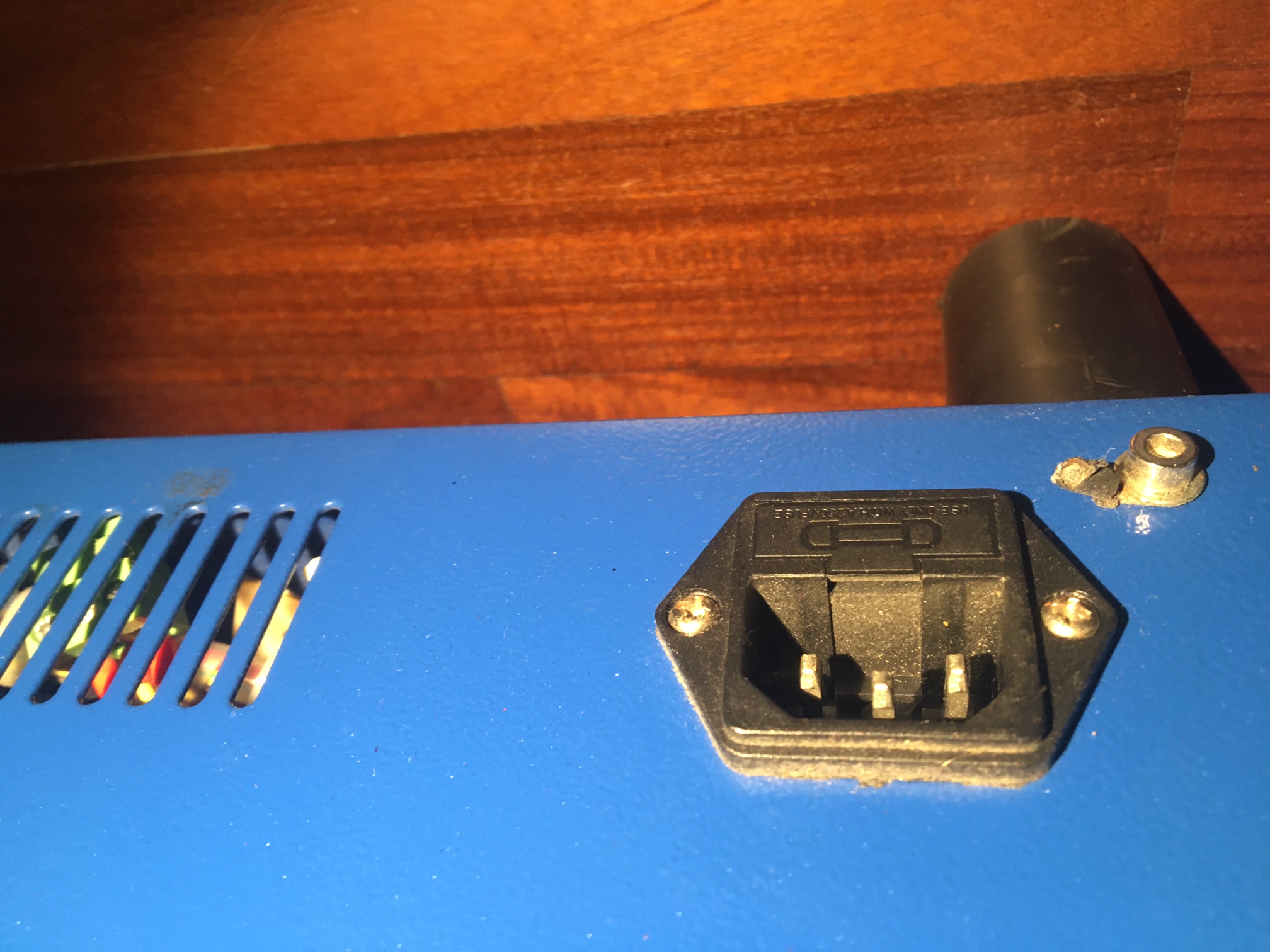
The laser PSU should have labels like IN, GND, P etc. Best is to take some photos and post them here so I can have a look,
Thanks Paul
Yes you need the second PSU because that's delivering power to the steppers. The MG3 board needs both 5V DC and 24VDC.
The laser PSU should have labels like IN, GND, P etc. Best is to take some photos and post them here so I can have a look,
Thanks Paul
Quote from matteo oddone on March 14, 2025, 12:11 amsteppers are running without the socondary psu (i'm pretty sure that my strange machine use it to light up a led bar a some fans in the case)
anywat ...i' screw the board ...and add photos here for a better check
sorry for being that rookie ....
steppers are running without the socondary psu (i'm pretty sure that my strange machine use it to light up a led bar a some fans in the case)
anywat ...i' screw the board ...and add photos here for a better check
sorry for being that rookie ....
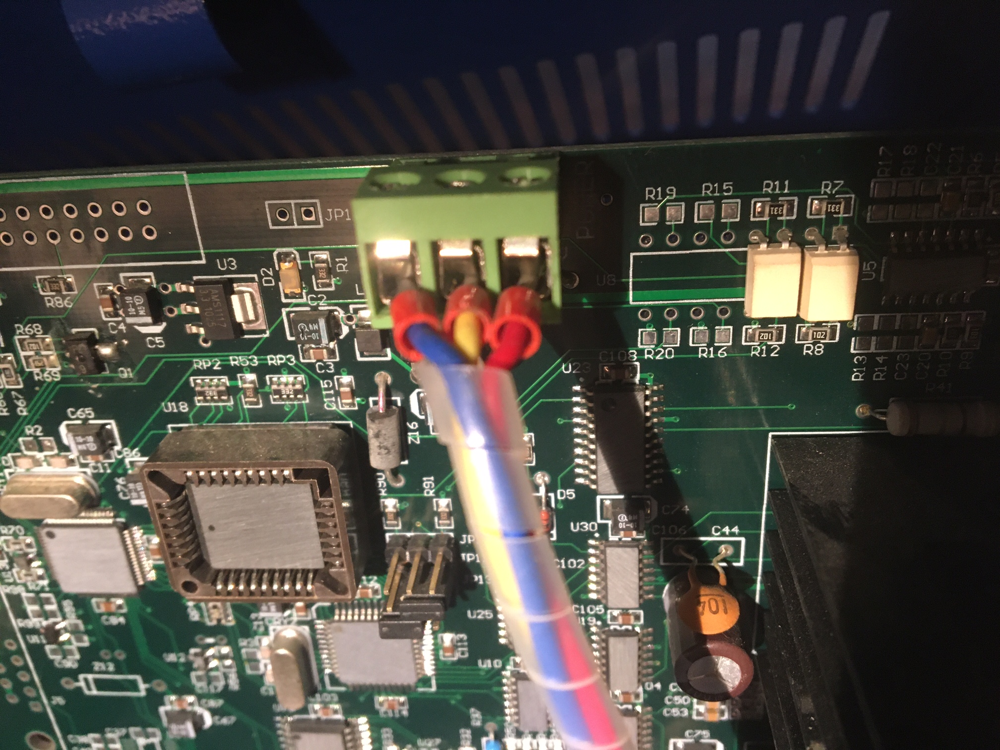
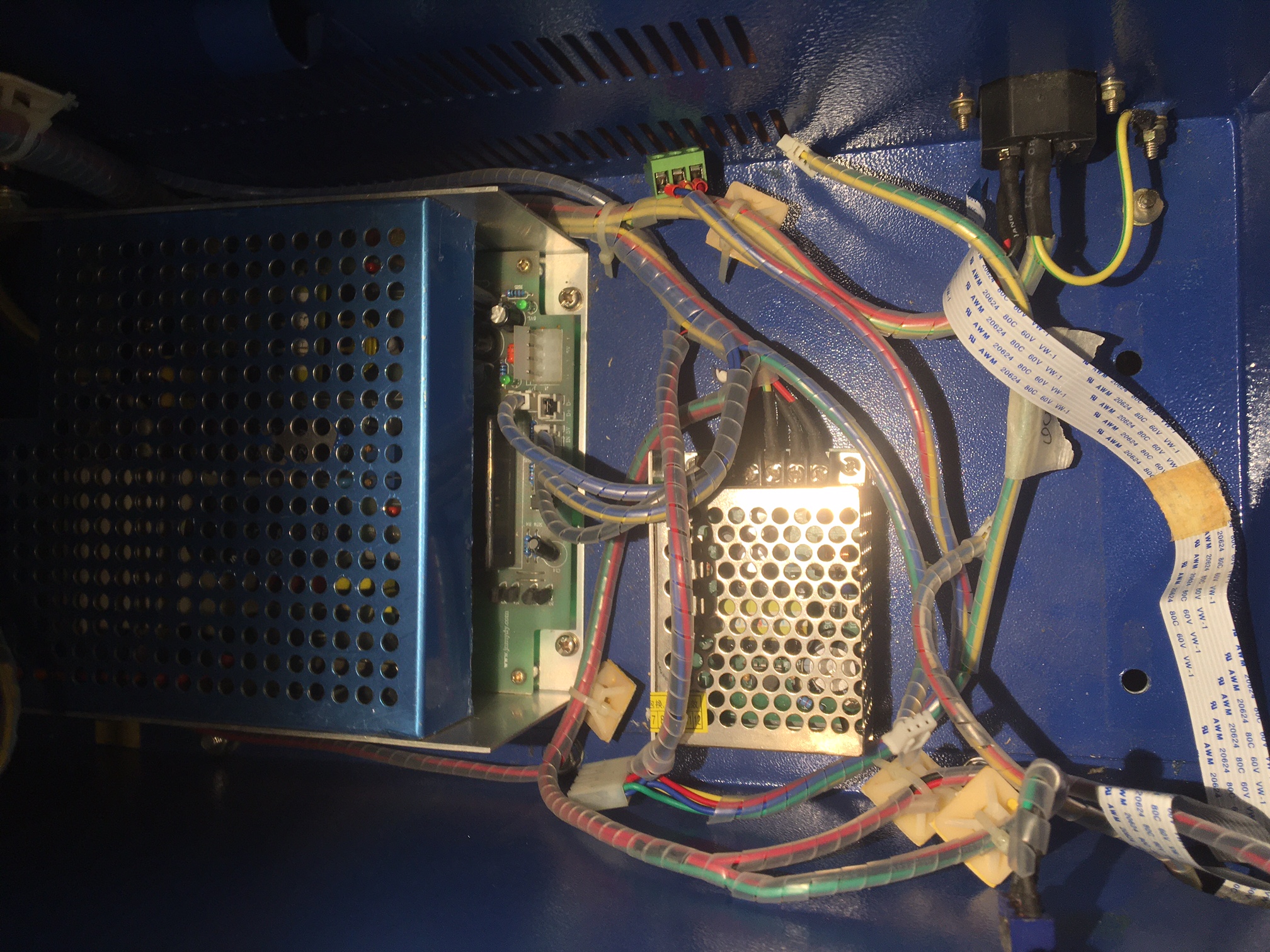
Quote from matteo oddone on March 14, 2025, 4:04 amthis what i have inside
(there's a image of the old board)
as you see ..i have 2 orphan connectiosn ...DAC and OUT (as showed from the removed old board)
i'll post another comment with the electronic's lid ..outside and inside
my best
this what i have inside
(there's a image of the old board)
as you see ..i have 2 orphan connectiosn ...DAC and OUT (as showed from the removed old board)
i'll post another comment with the electronic's lid ..outside and inside
my best
Uploaded files:


Quote from Paul on March 14, 2025, 11:19 amHi Thanks for that.
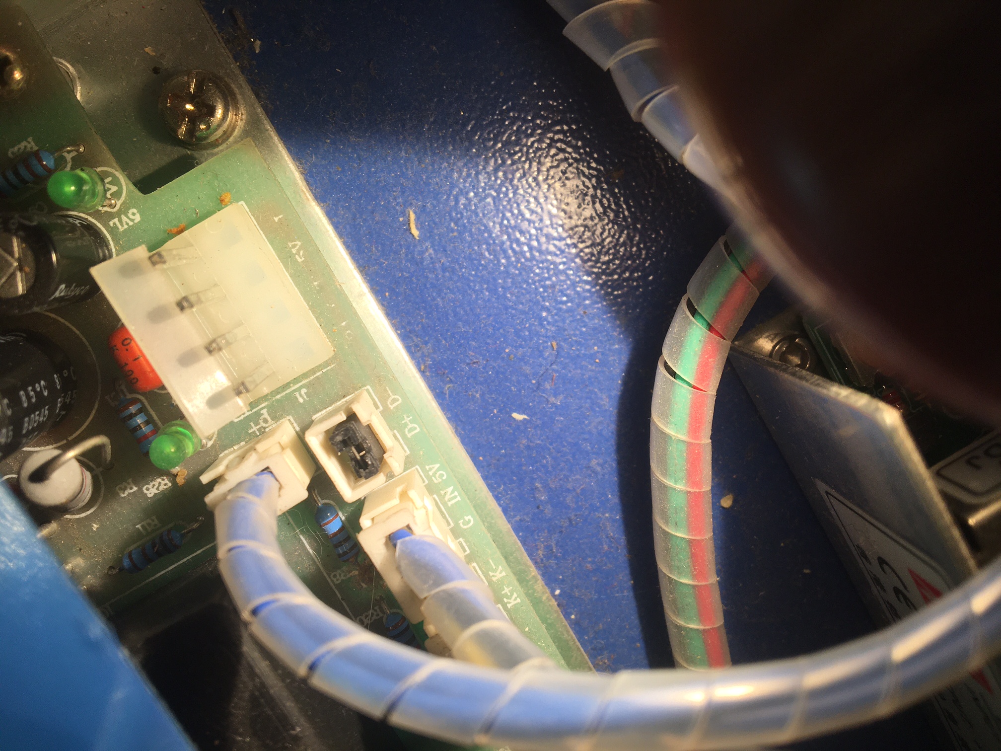
I can see the safety protect K connector above the D+ and D- connector. That is the connector that need to be bridged in order to get the laser beam armed (safety measure).
I believe on some machines the laser on safety is the K+ and K-. I don't know what the D+ and D- are but it looks like there is a black jumper in it. So reseat it to ensure it makes good contact. You can do a similar jumper P+ and P- to test it. The wire connection should end up on the control panel to a button switch (laser switch). Pressed in, it bridges the safety protect.
DAC out was the PWM from the old board to the IN connector on the Laser PSU. So MG3 does that now which is correct. The other orphan OUT was probably a connector to provide logical power to the buttons/controls. I don't believe this is an issue.
The Main power connector on the laser PSU is normally a 4 pin connector with LO (laser on control line) 5V, Gnd, 24V. However I cannot see this on the photo if you connected all 4 pins to the appropriate MG3 pins.
LO is a laser on or better laser enable signal. When LO is low 0 volt or to ground then the IN signal is processed and the laser beam is activated.
So I think you're nearly there. A simple multimeter would be a great help, they are very cheap. It helps you to see if the laser switch works and if LO is low/ or all 4 power connections are good between the Laser PSU and MG3.
Good luck and let us know how it went
Hi Thanks for that.
I can see the safety protect K connector above the D+ and D- connector. That is the connector that need to be bridged in order to get the laser beam armed (safety measure).
I believe on some machines the laser on safety is the K+ and K-. I don't know what the D+ and D- are but it looks like there is a black jumper in it. So reseat it to ensure it makes good contact. You can do a similar jumper P+ and P- to test it. The wire connection should end up on the control panel to a button switch (laser switch). Pressed in, it bridges the safety protect.
DAC out was the PWM from the old board to the IN connector on the Laser PSU. So MG3 does that now which is correct. The other orphan OUT was probably a connector to provide logical power to the buttons/controls. I don't believe this is an issue.
The Main power connector on the laser PSU is normally a 4 pin connector with LO (laser on control line) 5V, Gnd, 24V. However I cannot see this on the photo if you connected all 4 pins to the appropriate MG3 pins.
LO is a laser on or better laser enable signal. When LO is low 0 volt or to ground then the IN signal is processed and the laser beam is activated.
So I think you're nearly there. A simple multimeter would be a great help, they are very cheap. It helps you to see if the laser switch works and if LO is low/ or all 4 power connections are good between the Laser PSU and MG3.
Good luck and let us know how it went
Quote from matteo oddone on March 15, 2025, 12:03 ammy dear Paul
THANK YOU !!!
i put a jumper on the connector that is upper to D+ D- ...cause i saw P+
and know it works 😀
the prob with my laser was also that many marks are damaged or just not printed well
thanks thanks thanks !!!
My best
my dear Paul
THANK YOU !!!
i put a jumper on the connector that is upper to D+ D- ...cause i saw P+
and know it works 😀
the prob with my laser was also that many marks are damaged or just not printed well
thanks thanks thanks !!!
My best