Looking online and on Github…
The big strength of Grbl is that it runs on an Arduino and is therefore very accessible to the general public. Anyone can just jump into CNC and learn. Grbl’s biggest weakness is that it runs on an Arduino… hey stop there, didn’t you just say it’s biggest strength was… ? Yes, the issue here is that once you get started with Grbl on Arduino you run into performance issues, its memory ceiling, inability to extend features and lack of a user friendly interface. So when you want to advance and extend Grbl you need to look beyond the Arduino platform.
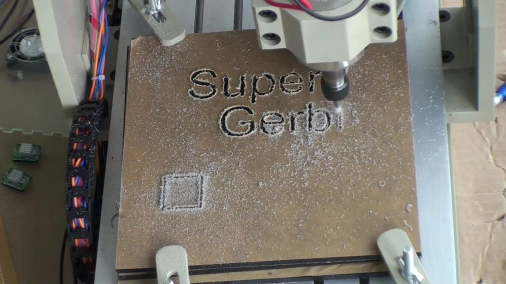
This article walks through the standard Grbl architecture, and some improvements that’ve been possible with the extra hardware capability of the Awesome.Tech Super Gerbil product.

I’ve sought proper design documentation for Grbl but have only found one article that describes the acceleration profiles part. The original 8 bit Grbl source code documents the code much better than most other repo’s do but the module names are often misleading and you can put only a limited amount of information in source code. There are simply no articles about how it all hangs together, the inner workings and secrets/hacks, or an architecture diagram.
To remedy this, I’ll share my insights from the last three months of preparing the Super Gerbil firmware. It should help with designing changes or improvements for your specific use case.
Firstly, let’s walk through the standard Grbl design, then we’ll move onto my goal of adding user definable subroutines or programmable switches, variables and conditions in my next blog. This will help us to move towards a BASIC style of programming, allowing the user to do canned style G-code programming. Such programming should be useful for repeating actions and simplifying repetitive work like cutting teeth on gears (cog wheels).
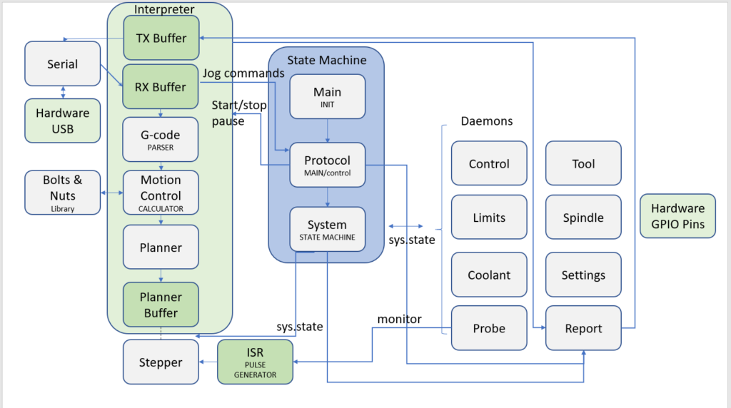
A few notes here: This is all my interpretation from reversed engineering the source code on Github. The names in the diagram are the actual names of the C# (pronounced as C sharp) modules. I have put a more meaningful functional name in capitals below them to guide your comprehension. It might not have been the developer’s intention or maybe it’s a misinterpretation on my side. However in the absence of any other diagram or description, this what we are starting with. Add your commentary and suggestions and I will endeavor to improve it!
Architecture

The architecture of Grbl consists of three fundamental blocks:
- State Machine: The Real Time control and execution of the state machine
- Interpreter: The interpreter and streaming of the G-code
- Daemons: Peripherals or daemons that do their specific jobs: Report, Settings, Tool, Limits, Coolant, Probe, Steppers, Spindle etc. not all have been depicted here like ‘eeprom’ in order to simplify the diagram
State Machine

The state machine keeps track of the real time state of Gerbil, the control buttons, the overrides of feeds, spindle and buffer. It’s rather complex and hard to understand since the sys.state is being interrogated by all daemons. So it’s basically an interface based on status registers.
Main – This is the initialization of Gerbil and it set up the processes of the controller. Despite being Main it never loops and is only visited again when the system gets a reset or abort by the user or boots up from powering up.
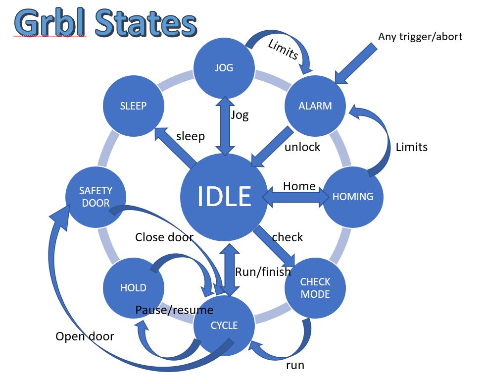
Protocol – This is the real ‘Main’ in terms of the embedded ‘C#’ software. This routine loops forever like a normal Main does and it executes the state machine ‘System’. It checks for Alarms, Jogs, and Overrides and set the various flags to make them active or actionable. For example, the state machine is set to CHECK_MODE then the peripherals don’t actually execute or set a GPIO pins etc. So the systems runs without doing anything.
System – This is the heart of the Real Time system that allows Gerbil to operate in a Real time fashion.
System States – IDLE, ALARM, CHECK-MODE, HOMING, CYCLE, HOLD, JOG, SAFETY DOOR and SLEEP

Interpreter

This is the conveyor belt (big block on the left of the architecture diagram) that takes the G-code from the USB buffer, parses the G-code for syntax errors, calculates the arcs, speeds and motion profiles (acceleration), plans the motion and feeds it to the planner buffer for consumption by the stepper interrupt routine.
Serial – reads the USB port and stores the data in a buffer. It keeps a counter to prevent a buffer overflow. At the point of overflow, the serial process will pause until the buffer has room.
G-code – This is the parser that inspects the G-code and determines whether its syntax is correct. It sends information to the report daemon which is put back on the USB TX buffer so the G-code sender application and user gets feedback.
Motion control – This is the numeric cruncher that calculates the actual motion that the stepper can carry out. It uses smart approximation calculus to reduce the amount of processing power required and ensures that the calculation keeps up with the speed of the motion (e.g gantry).
Bolts and Nuts – This is a supporting library for the Motion Control calculator. These are mainly macros for the calculator.
Planner – This is the adjustment of individual motion parts (blocks) into one consecutive block of movements. The process finds the entry and exit speeds for each motion block and adjusts them to achieve smooth motion across the blocks. This means the planner goes twice through the entire buffer:
* first to fill all block segments in the planner buffer
* backwards from the end segment to the start segment, matching the entry and exit speeds at each junction so no sudden changes are experienced.
Stepper – The stepper is a daemon process (peripheral) that takes the planner buffer motion and executes them. This is where the hand over from calculations to physical world process execution happens. See below.
Daemons

The daemons are just routines that do a very specific job. Thankfully the names of those jobs match their roles very well so you can locate them quickly in the code.
Stepper – The stepper is a daemon process () that is driven by two parts: a planner buffer and an interrupt timer (or Interrupt service routine). It just runs in the background of the processor and empties the planner buffer and driving the stepper motors. This is the heart of the motion system.
Limits –
The limits module is a daemon process () that is driven by two parts: 4 GPIO inputs and an interrupt on GPIO detection (or Interrupt service routine which is triggered by a GPIO change). It only runs when the processor detects a falling signal on those specific ports (Pause, Resume, Abort, Safety Door). So it’s hardware controlled by the processor’s internal microcode.
Control – This daemon monitors the control data which is funneled to a designated GPIO pin for an interrupt input. It’s very similar to the Limits module except it reads control buttons. It’s an alternate function (ST’s jargon) in the STM32 processor. This means that an internal ISR vector is routed to take triggers from a GPIO port. I probably would have called it a combined peripheral function if I had worked at ST 🙂
Note: You can only configure/initialise the trigger function for GPIO ports in one spot otherwise you overwrite the previous config and loose previous configured ports. This is an undocumented ‘feature’ in STM32 and caused me a hell of time to figure this out. So the assigned Limit GPIO pins which are working on the same trigger interrupt principle need to be configured with Control GPIO pins in a combined initialisation routine which makes it complex to read the ported code unless you understand the above mentioned constraint!
Coolant – This daemon just turns the Coolant ports on or off based on the G-codes M7, M8 and M9.
Probe – This daemon is a mini program that executes a set of Z-moves and allows the user to read the tool’s offset based on a GPIO Pin becoming active. It’s a macro which makes smart use of the Stepper ISR by utilising the ISR time loop as a state monitor. It’s a cuckoo bird! Just riding the ISR for its own purposes.
Settings – This daemon can read the settings for the controller such as the max travel, acceleration, speeds etc. It reads and stores the information in the flash ROM of the processor. Note: all settings are stored as $xxx where xxx is a number. The text you see in your G-code sender when issuing a $$ (give me the settings command) are from the G-code sender itself. So when we add new $ settings, those are not getting any description from the G-code sender. We added our text behind it so you know what it means.
Report – This daemon does realtime reporting to the G-code sender app to inform the sender of the current co-ordinates (DRO function), offsets, alarms, G-code parser errors and status. It is also responsible for displaying the settings stored in flash rom.

Spindle – This daemon generates the PWM which is funneled to a designated GPIO pin. It’s an alternate function in the STM processor. This means that an internal timer peripheral is routed to a GPIO port. I’ve extended the Gerbil version of grbl to make the PWM frequency configurable between 60 Hz to 80 kHz via the settings daemon.
Tool – This Gerbil-specific daemon allows the user to build an Automatic Tool Changer (ATC). It toggles the GPIO pins designated for M6 and T<nnn>. Toggling refers to turning on or off, or on and off with a specific duration. T<nnn> toggles the GPIO pin designated for T nnn times so it can drive a stepping function (valve or solenoid).
Conclusion
I hope the above description helps those seeking to understand GRBL. It’s certainly a complex endeavour, and requires a mix of software development experience, as well as knowledge of CNC systems and controller hardware.

Can I run this from a Mac?
Hi Nick, yes LightBurn, Inkscape and any G-code sender (Mac) have Mac versions.
Thanks.
High
I am interested in a position feedback loop for each axis. The objective is to do a realtime correct for backlash. I wonder if you have enough hardware IO pins to realise. What part of the code is the best place to start. I am new in this field and working on a linear encoder. I am pleased with your explanation of the code Thank for that in advantage
Thank in advantage
John Nivard
Hi John, there are two options to use direct feedback. You can have a stepper motor with a feedback electronics builtin so you don’t need to adapt the grbl firmware. The motor adjusts for missed steps by itself. Or you can use a feed back from an encoder into grbl. You need to modify stepper.c where the steppulses are generated. Realtime feed back in the pulse routine can compare the generated pulses and the received pulses from the encoder. The appropriate axis is also included in the routine (so you know which encoder count to compare with). The Super Gerbil is build for 5 axis on a F103 so for 3 axis you should have enough pins available.