
The purpose of a door safety switch is to prevent users being exposed to the laser beam while the laser is in operation. The swich is mounted on the lid, and so is sometimes called a lid switch. If a person opens the lid then the controller will halt its operation and shut down the laser beam. Closing the lid and pressing resume (either within the software interface or the physical resume button) will continue the laser operation.
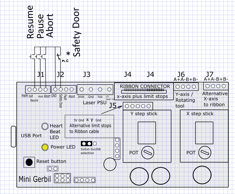
To install a door safety switch, you need to wire up a microswitch to the pins as shown on the drawing below. To restart the laser, the resume function waits a few seconds (dwell time) before resuming. This originates from its CNC heritage, where a system waits for the spindle to be ready.
If you have Mini Gerbil firmware update 12353 or beyond, you’ll need to configure $97=1 to enable the safety door switch.
Technically speaking you could perform a similar function to the controller based door switch (below) by wiring the pause button as a door safety switch, but that’s not covered in this blog.
In GRBL, adding a safety lid feature is done via a NC microswitch. NC stands for normally closed at rest (with no pressure on the switch). Since we mount the NC microswitch on the K40 chassis near by the lid, the lid will press the micro switch when the lid is closed, so the contacts will be open when the lid is closed. When a user opens the lid, the micro switch is released and goes into its NC state closing the contact.
Remember that the Safety Door Switch triggers the alarm, but closing the lid doesn’t stop the alarm. You’ll also need to press ‘resume’ in the software (such as Lightburn), or wire in the Resume button to stop the alarm.
This GRBL implementation of the door safety switch is counter to standard industrial safety design. So think of it more like a convenience reminder than a true safety feature. In a robust safety design, if the safety circuit itself becomes open-circuit, the dangerous element will be locked out. This design recognises that when wiring faults occur, they’re more likely to cause open circuits than closed circuits. The most likely reason that GRBL chose not to implement the standard industrial safety design is because many GRBL users don’t want to use a safety lid switch, and the non-standard avoided presenting those users with a safety alarm lockout until the user implemented a lid switch (or at least a short circuit). Having said that, the whole idea of implementing a safety switch via a microcontroller and firmware is counter to standard industrial safety design anyway – safety hates complexity. So the better solution is to simply utilise Option 1 below.
If you’d prefer to use the standard safety design, there’s a few options:
- design your own safety switch circuit independent of the controller. This could utilise a Normally Open (N.O.) contact on the limit switch in series with the laser enable switch on the front panel, the emergency stop switch or the WP (water protect) terminal of the power supply. When the lid opens, the terminals are open, and the laser cannot fire. Ensure you don’t switch mains voltage through the safety switch – this would introduce risk of electrocution should the wiring degrade.
- wait until a GRBL firmware update makes the safety design configurable
- design a DIY circuit to invert the signal between the lid switch and the Mini Gerbil. A theoretical downside is accidental disconnection of the circuit from the Mini Gerbil and this would deactivate the safety feature.
- there may be a mechanical solution – if somehow the switch can be installed such that the switch is pressed in when the lid is opened. But don’t make anything fancy (which could go wrong) and thus provide a false sense of security.
Assuming you’re happy with the non-standard safety design, back to the current GRBL design: The wiring is simple – the micro switch NC pin goes to the safety door pin on the Mini Gerbil and micro switch Common in goes to ground on the Mini Gerbil. The Safety Door and Ground pins are on break out connectors called J1 and J2. Make sure that you bundle the wiring neatly together and away from the laser output and return line (high tension cables also known as high voltage). Also keep the lines away from the mains AC wiring so it does not pickup any noise signals.
Aim to use KK254 Molex type connectors or similar (example from Australian retailer Jaycar https://www.jaycar.com.au/4-pin-0-1-header-with-crimp-pins-2-54-pitch/p/HM3404) The pitch is 2.54mm. Farnell and Element14 and RS online have them as well. (Molex, KK 254 Female Connector, 2.54mm Pitch, 4 Way, 1 Row)
In the picture there are 2 abort pins
1 on j1 and one on j2.
On mine, received last week there is only abort on j2.
On j1 it is labeled wp.
Which surprises me because when it is waterprotect I would have expected it to be shortens to ground.
So my question is simple. What is the wp pin on j1 used for?
Grt. Erik
Hi Erik,
We had a few requests for a WP output so you could use it to drive a solid state relay to switch on a pump or air assist (M7 or M8 command).
The firmware is being upgraded to support this and other additional features like ability to invert PWM/LO logic and bug fixes. It is still under test before being released.
Cheers, Paul
Hello, is it possible to make it work with a N.O. microswitch? For applications like these it is mandatory (at least in the commercial space) to make the wiring fault proof. What i mean is the following: If the wire to the safety switch somehow broke off you would be left with a permanent open curcuit state, which the controller would interpret the same way it would interpret a closed lid (laser would continue firing). A N.O. microswitch would circumvent this issue since in closed lid state you have a closed circuit, and in open lid or broken wire state you have an open circuit. But for that to work you would have to invert the signal in the controller. Greetings, Nico
Hi Nico,
I’ve edited the blog and outlined some options to achieve your goal. Hope it helps? We’ve added a N.O. safety switch configuration option to our firmware to-do list, but can’t promise a completion date.
Regards,
Dan