Introduction
The biggest advantage of the GBRL controller based on the 328PB chip is it’s ability to produce 16 bits PWM at various frequencies. However to harness that feature you need to understand how to program it.
The problem of understanding and programming the 328PB lays in it’s multiplexed structure. There are not enough registers and pins available for everything and they are placed in odd places. That’s why we had to swap out the USB port to get access to the pins for PWM (Timer 3 or 4).
Internally there is also a lot of multiplexing or sharing of registers which forces you to choose for certain outports. For example you can use a register to load the PWM value but sacrifices that register to drive an output (i.e. OCR4A). Unfortunately this has been described in such incomprehensible way in the data sheet, that you get lost. Ideally you should have an feature/register overview so you know the building blocks that are or aren’t available for a function. It is a bit like lego and using the right bricks to build it. I have tried in this article to show you that.
PWM modes
There are a few PWM modes: frequency correct pwm, phase correct pwm, freq and phase correct pwm and fast pwm.
The frequency and phase correct pwm ensures that the clock timer signals and output signal are complete and don’t skip a clock pulse or phase when the pwm value changes. They use a technique called dual slope to achieve this. In a nutshell the timer counts up and at a set value the output is switch on and after reaching the full count (TOP), the timer counts down and at the same set value, the output switches again to zero. The dual slope is the up and down counting for one output cycle. This divides the clock signal by 2 so all the pwm frequencies for freq/phase correct are half of those of the single slope PWM generation frequency. Single slope means here that we only count up till the Top and restart. This is being used for fast PWM and is called fast since the pwm output freq is double of freq/phase correct pwm.
PWM frequencies
PWM frequencies are generated by a clock prescaler which divides the CPU clock by 1, 8, 64, 256 or 1024 cycles. This allows to set the PWM frequency to something that can be used by the receiving system. In our case the laser power supply. Since that system has a very basic driving circuit, it can only accept a small frequency range (60 to 244 Hz).
Programming the 328PB PWM registers
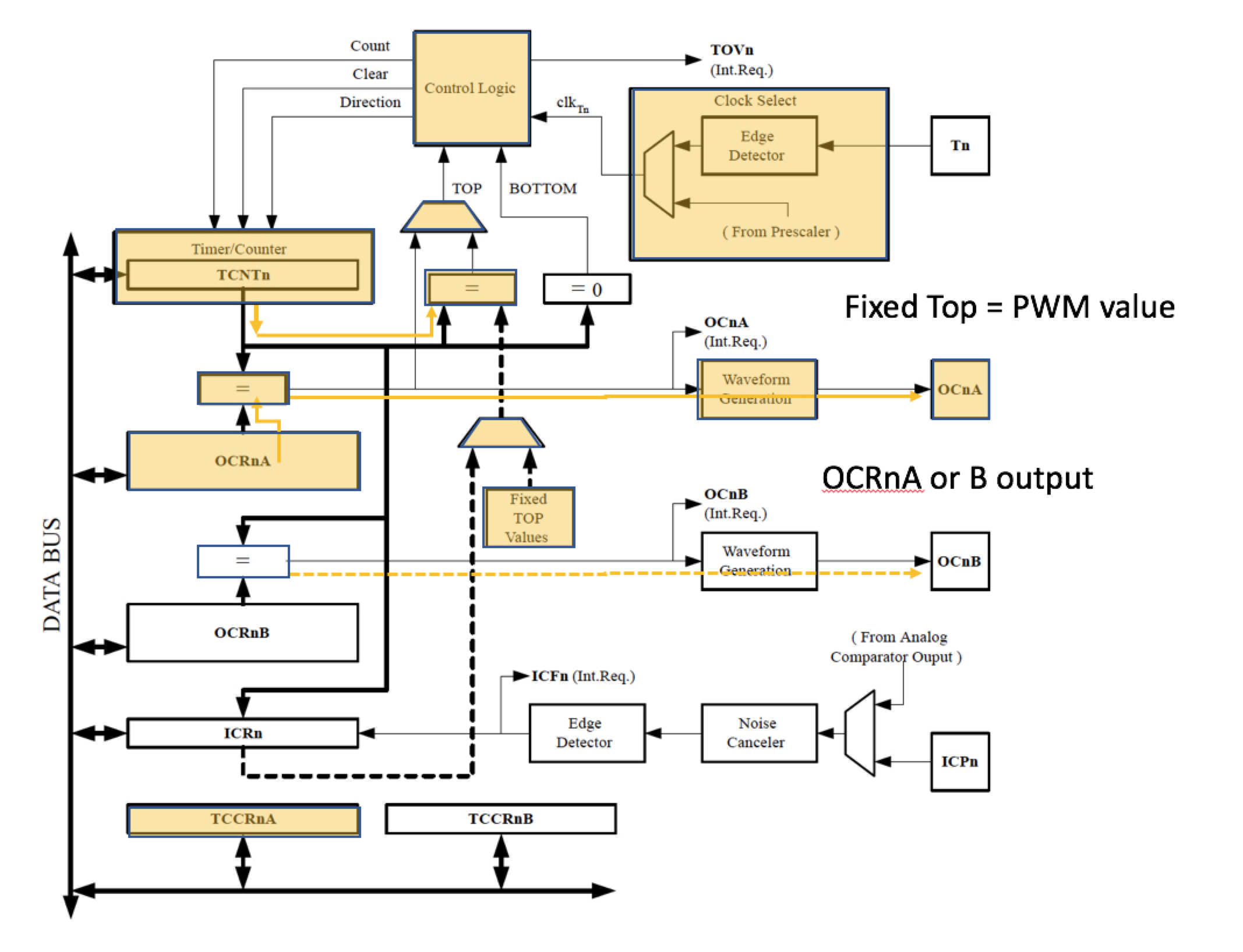
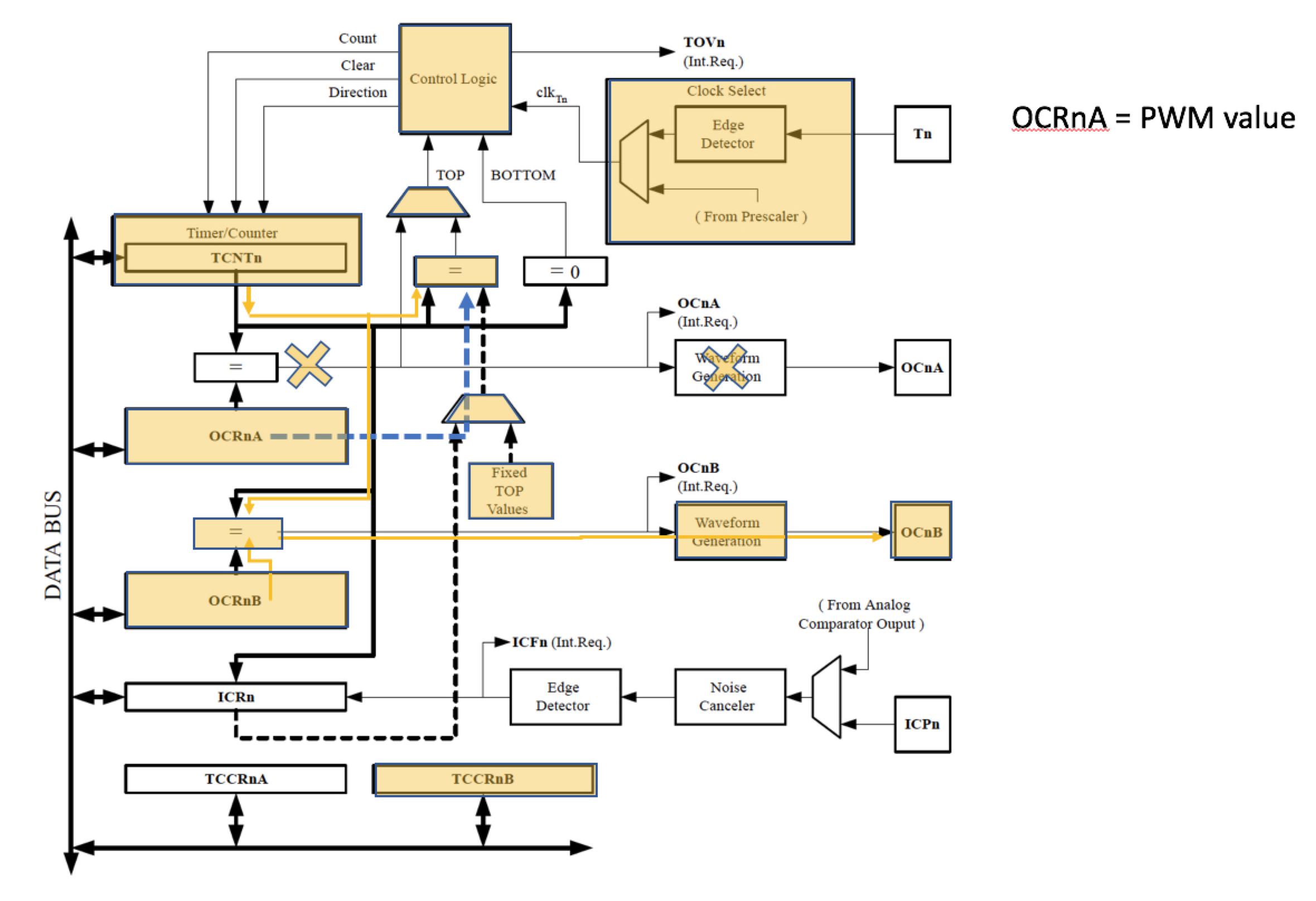
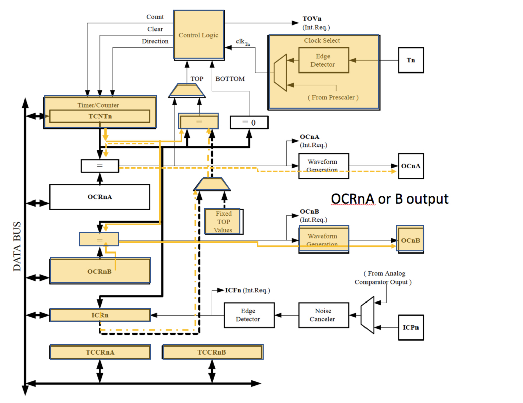
To understand the programming of the PWM feature, you need to understand the register block diagram below. I have divided this diagram into three different configurations with a Tan colour so you can understand what is being used in a certain PWM mode.
Fast PWM with fixed TOP value

Note we use a fixed TOP value to compare.
Fast PWM with variable TOP value

note we use the OCR4A register as Top value and renders it unavailable as output…
Frequency/Phase correct PWM

Note we can use a fixed Top value or use register ICR1 as a place to store the Top value (either OCR4A or B can be used to output the pwm)
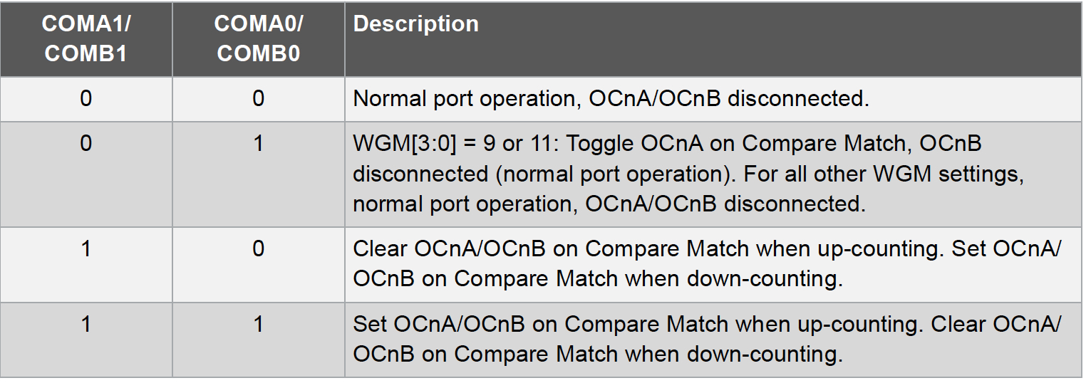
Fast PWM compare register configuration
COM4A1 (we assume COM4A0 = 0 at init so only need to set COM-Timer number-A1)


Phase correct/Freq correct and Phase+Freq Correct compare register configuration
COM4A1 (assume COM4A0 = 0)

PWM modes with WGM (Timer Number)3,2,1,0 (e.g. WGM43,42,41,40)


Note: CTC mode – has the value of “immediate” which means the value is loaded immediately into OCRn port which can lead to errors (no double buffering, so counter compare does not happen until another full clock cycle). Mode 0, is a direct output mode and mode 13 is not implemented or available that leaves us with 14 modes and 6 usable prescaler values = 84 combinations (roughly only 7 works for the K40). The method with ICR1 did not work when I tried it, probably because of Interrupt routines in Grbl do reset the interrupt registers or configure them.
How has this been implemented in the Gerbil code…?
CPU_map.h has preconfigured register masks so we can choose which mode we want ($28 setting in Grbl). We assume this example that we use timer 4 with PWM output on D1.
#define SPINDLE_TCCRA_REGISTER TCCR4A // we use timer 4

#define SPINDLE_TCCRB_REGISTER TCCR4B // we use timer 4

#define SPINDLE_OCR_REGISTER OCR4A // we use timer 4 - pwm value

#define SPINDLE_COMB_BIT COM4A1 // use compare timer 4
// We use different masks for TCCRA and TCCRB to set the PWM mode and the prescaler
// These features are configured across the two registers TCCRA and B
// In the main program we can choose which configuration we apply Mask A, B, C etc
#define SPINDLE_TCCRA_INIT_MASK_1 ((1<<WGM41)|(1<<WGM40))// Configures phase correct PWM mode.

#define SPINDLE_TCCRB_INIT_MASK_D ((1<<WGM42) | (1<<CS40)) // 1 Disable prescaler -> 15kHz

#define SPINDLE_TCCRB_INIT_MASK_C ((1<<WGM42) | (1<<CS41)) // 1/8 prescaler -> 1.953kHz (reduced gray)

#define SPINDLE_TCCRB_INIT_MASK_A ((1<<WGM42) | (1<<CS41) | (1<<CS40)) // 1/64 prescaler -> 244Hz (best working)

#define SPINDLE_TCCRB_INIT_MASK_B ((1<<WGM42) | (1<<CS42)) // 1/256 prescaler -> 61Hz

#define SPINDLE_TCCRB_INIT_MASK_G (1<<CS40) // 1 Disable prescaler -> 7.5kHz

#define SPINDLE_TCCRB_INIT_MASK_F (1<<CS41) // 1/8 prescaler -> 1kHz (reduced gray)

#define SPINDLE_TCCRB_INIT_MASK_E ((1<<CS41) | (1<<CS40)) // 1/64 prescaler -> 122Hz (best working)

#define SPINDLE_PWM_DDR DDRD

#define SPINDLE_PWM_PORT PORTD // This sets Port D as the PWM output

#define SPINDLE_PWM_BIT 1 // This sets the pin 1 as PWM output port D
Note: “1 << Register” sets a register bit of TCCR to “1”
Spindle_control.c code:
void spindle_init(uint8_t pwm_mode) // give pwm_mode to the init routine to set the appropriate mask A, B etc

SPINDLE_TCCRA_REGISTER = SPINDLE_TCCRA_INIT_MASK_1;

switch (pwm_mode) {

case 0:SPINDLE_TCCRB_REGISTER = SPINDLE_TCCRB_INIT_MASK_A;Break;

case 1:SPINDLE_TCCRB_REGISTER = SPINDLE_TCCRB_INIT_MASK_B;Break;

etc...
Further we need to ensure that the pwm value is a 16 bits format:
uint16_t pwm_value // replace all uint8_t values for uint16_t
