
Ok, this is the big one, the most complex part of your Personal Particle Accelerator. You’ll want a couple of straight hours to spend on this.
Required Tools / consumables
- Fine tip soldering iron
- Needle nosed pliers
- Side cutters
- Fine tip flat screwdriver to adjust SMPS
- Fine tip phillips screwdriver for wire connections
- Fine solder
- 12V DC power supply
- Multimeter Hot air gun (/hair dryer)
Overview
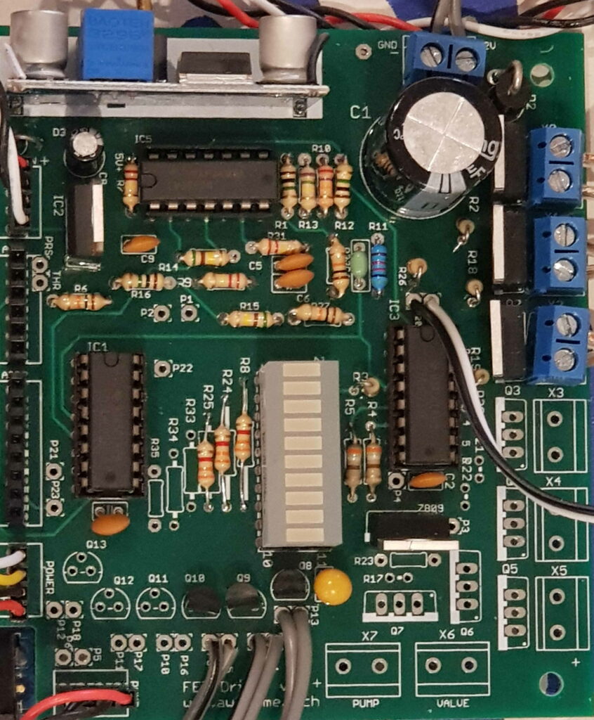
These instructions cover the standard kit with 3 electromagnets and thus only requires 3 sets of supporting components (MOSFETS, transistors and resistors etc) – see photo below. If you’re building the Super size PPA, you’ll need to double the relevant components – see the Super Size PPA specific documentation.
Assembly sequence
Perform the soldering and assembly in the sequence below, which has been chosen to start with the lowest profile components first, working up to the larger components. This makes soldering easier if the board is placed on a flat surface while soldering.
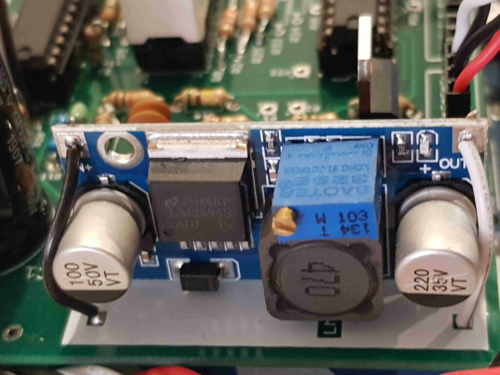
The small circuit board within its own packed is the Switch Mode Power Supply (SMPS). Remove it and connect the input terminals to a 12V DC supply and your multimeter in voltage setting to the SMPS output. Adjust the SMPS’s small adjustment screw with a screwdriver until the output is 8.5V. Do not solder into the main PCB now. Note that the SMPS adjustment screw seems to take a lot of work to prepare – I have had to rotate 30 or more times in each direction to get the SMPS output voltage to start responding to the rotation. Please be patient and keep turning your screwdriver until you see a response.
Insert and solder the following components.
| Component | Value | Identifier | Notes |
| R1 | 1M | Brown, black, green, gold. | Resistor to positive terminal of op amp configured as comparator |
| R3 | 390R | Orange, white, brown, gold. | Common Ground bar graph resistor |
| R4,R5 | 390R | Orange, white, brown, gold. | Bar graph indicator resistors |
| R8,R24,R25 (nearby LED bar) | 3k3 | Orange, orange, red, gold. | Resistors to bias Strobe transistors |
| R10 | 27k | Red, violet, orange, gold. | Resistor divider for comparison reference point |
| R11 | 40k2 | Yellow, black, red, red, brown. | Resistor divider for comparison reference point |
| R2, R18, R19 | 300R | Orange, black, black, black, brown. OR Orange, black, brown, gold | Resistors to bias MOSFETs |
| R26 | 10k | Brown, black, black, red, brown. | Pull down resistor for enable switch |
| R6 | 10k | Brown, black, black, red, brown. | Pull up resistor as part of RC network during Arduino reset |
| R31 | 220k | Red, red, yellow, gold. | Input resistor to op amp configured as tacho |
| R32 | 10k | Brown, black, black, red, brown. | Feedback resistor in op amp configured as tacho |
| R9 | 220k | Red, red, yellow, gold. OR Red, red, black, orange, brown | Feedback resistor in op amp configured as tacho |
| R7 | 220k | Red, red, yellow, gold. OR Red, red, black, orange, brown | Resistor for positive input to op amp configured as tacho |
| R12 | 1M0 | Brown, black, green, gold. | Input resistor to negative terminal of op amp configured as comparator |
| R15 | 510k | Green, brown, yellow, gold OR Green, brown, black, orange, brown | Resistor to reset op amp configured as latch |
| R27 | 10k | Brown, black, black, red, brown. | Resistor to reset op amp configured as latch |
| R16 | 1M0 | Brown, black, black, yellow, brown. OR Brown, black, green, gold | Resistor for negative terminal of op amp configured as latch |
| R13 | 750k | Violet, green, yellow, gold. OR Violet, green, black, orange, brown | Input resistor to op amp configured as latch |
| R14 | 510k | Green, brown, yellow, gold OR Green, brown, black, orange, brown | Feedback resistor for op amp configured as latch |
| C1 | 2200uF | 2200uF electrolytic capacitor | Note polarity. Bulk capacitor to support electromagnet operation |
| C2 | 0.1uF | 104 | Decouple caps for IC |
| C3 | 22uF | 226 Tantalum cap | Note polarity is such that the positive end of the capacitor is towards the nearest edge of the board. Output cap for 7809 strobe LED supply |
| C4 | 2n2 | 222 | Arduino reset timing capacitor |
| C5, C6 | 0.1uF | 104 | Time contstand for Tacho circuit |
| C7 | 0.1uF | 104 | Decouple caps for IC’s |
| C8 | 4u7 | 4.7uF electrolytic capacitor | Note polarity. Input Cap for 7805 |
| C9 | 0.1uF | 104 | Output Cap for 7805 |
| Q0-Q2 | IRL2703 | IRL2703 TO-220 | Note polarity. Logic Level MOSFET |
| Q8, Q9, Q10 | 2N3904 | 2N3904 small transistor | Note polarity. BJT transistor for Strobes |
| D2 | 1N5408 | 1N5408 | Protection against reverse polarity from 12V supply. Note polarity: solder with diode’s cathode (white ring) down towards the white ring on PCB |
| D3 | 1N4004 | 1N4004 | Ensures the SMPS supplies the Arduino, not the other way around. Note polarity: solder with diode’s cathode (white ring) down towards white ring on PCB |
| 4 pin header terminal | Solder to Power position | ||
| 4 pin header terminal | Solder to Thrcon position | ||
| 4 pin header terminal | Optional solder to Pump position | ||
| 2 terminal screw connectors | N/A | Blue 2 pin connectors | Solder to positions X0, X1, X2 and the (12V GND). Screw terminal should face outward from PCB. |
It’s easy to get into the habit of trimming leads as you solder them. But whatever you do, don’t trim these leads!
| 6 pin and 8 pin black sockets for Arduino | N/A | 6 pin and 8 pin black sockets for Arduino | Solder into ARD1 and ARD2 sockets !! Do not trim the leads, they are used to connect to the Arduino !! |
| 14 pin IC socket for IC5 | Black 14 pin IC socket | Solder to position, with orientation mark as per silk screen | |
| 16 pin IC sockets for IC1 and IC3 | Black 16 pin IC socket | Solder to position, with orientation mark as per silk screen | |
| 20 pin IC socket for BAR1 | Black 20 pin IC socket | Solder to position, with orientation mark towards pin 1 noted on Silkscreen |
STOP ! Before proceeding, did you complete the procedure to set the SMPS voltage to 8.5V ? Voltage should be set prior to soldering. SMPS Daughter board to supply Arduino and 5V regulator. Note polarity. Position SMPS on long edge, with negative (-) terminals downward to PCB, soldered into pads centremost on the board. The screw should face outwards from the PCB. Solder short insulated jumpers from positive terminals of SMPS to nearby pads towards edge of the PCB.
| Power Supply Module | SMPS Daughter board to supply Arduino and 5V regulator. Note polarity. Position SMPS on long edge, with negative (-) terminals downward to PCB, soldered into pads centremost on the board. The screw should face outwards from the PCB. Solder short insulated jumpers from positive terminals of SMPS to nearby pads towards edge of the PCB. Solder thick leftover component leads between the SMPS’s negative terminals and the main PCB. | |
| IC2 | 7805 | 7805 Note polarity. 5V regulator for TTL chips |
| 7809 | 7809 | 7809 Note polarity. 9V regulator for Strobe LEDs |
| Dupont wire for enable switch | Solder two conductor cable with Dupont sockets to P19 and P20 | |
| Switch | Plug the Dupont connector sockets onto the centre switch pin and either side pin (doesn’t matter which one). If the connections are loose, apply a drop of super glue across the black plastic Dupont connector and the red switch casing. The switch toggles the Enable pin of the output of the 74HC238 decoder used for the Electromagnets. This switch is useful to temporarily disable the electromagnets without powering down the PPA. |
Half way point testing
If you’re using a laboratory power supply with inbuilt current display, set up Supply 12V DC to the power connector with indicated polarity.
If your power supply doesn’t have an in built current display, wire your multimeter in current measuring mode and wire in series with your power source.
Confirm current draw is under 20ma, indicating the SMPS is active but unloaded. If current draw is larger than this, quickly de-power and review your work for error.
Integrated Circuit installation
Now insert the IC’s and LED Bar Graph
| IC1 | 74HC238 | 74HC238 | Decoder for Strobes Note polarity: chip orientation must match the pcb silkscreen |
| IC5 | LM3900 | LM3900 | Norton Op amp for Protection Note polarity: chip orientation must match the pcb silkscreen |
| IC3 | 74HC238 | 74HC238 | Decoder for MOSFETS Note polarity: chip orientation must match the pcb silkscreen |
BAR1 DC10SURKWA Common Ground bar graph. Note polarity: chamfered corner is pin 1, shown in top left of above photo.
Install standoffs
Install two of the 25mm M3 screws from the Nuts and Bolts bag through the PCB’s two holes, and secure with an M3 nut each side of the PCB. The screws will act as stand-offs to lift the non-Arduino side of the board.
Setup Strobes
The strobe LEDs flash from the same triggers that drive the electromagnets. The strobes consist of the aluminium light pipe, LED and resistor. The light pipe reflects the LED’s light and abuts the PPA’s main tube at the angle of total internal reflection, to encourage the strobe’s light to travel down the tube.
- Identify the grey two-conductor cable from the Wires bag. For the Standard PPA, cut three equal lengths around 33cm each. For the Super PPA, cut into six lengths of around 50cm. The wire specs are listed further below.
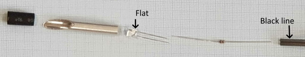
- At one end of each length of wire, separate the two conductors 50mm, and cut short the black striped wire by 10mm
- Strip and tin each wire conductor at both ends
- Cut the LED leads to 5mm
- Solder the small 100R resistors (brown, black, black, gold ) to the LED cathode (with flat side on LED body)
- Solder the other end of the 100R resistor to the shorter lead with black stripe
- Solder the LED anode (non-flat side) to the longer grey conductor.
- Trim the supplied heatshrink from the lightpipe packet in thirds.
- Insert the LED into the flat end of the lightpipe as far as it will go.
- Slide one of the heatshrink pieces over the aluminium tube so half of it is over the aluminium tube and the other half over the LED leads. Apply hot air with hairdryer to shrink the heatshrink. This will secure the LED in place
- Repeat the above steps with the other two strobes
- Solder the other end of black-striped wires to P7/P8/P9 on Output board PCB
- Solder the other end of non-black striped wires to P13/P14/P15 on Output board PCB
Wire specifications: the wire provided in the kit was https://www.jaycar.com.au/light-duty-fig-8-speaker-cable-sold-per-metre/p/WB1702 . See the link’s specifications tab for full details.
Note that the strobes’ very low duty cycle means that almost any wire can be used.
I know that light pipes (first 3) go onto (black stripe side) P7/P8/P9 and P13/P14/P15 prospectively.
P9 and P 10 do not make sense with how the others are laid out. P7 and P13 are paired next to each other, P8 and P14 are as well, however P 9 and P10 on the instructions do not make sense (see sentence prefaced by number 13 on the light pipe section).
Where does the other 3 light pipes go for the advanced projects? I see P1, P2, P3, P10, P11, P12, P16, P17, P18, P21, P22, P23,PRS, THR are all open.
There is also R23, R17, Q7, Q6, X7, X6, Pump, GND point, and Valve all open with no listing of components that go there. Can I get a confirmation that is true.
Hi Chris,
I’ve updated/corrected instruction 13 to read “Solder the other end of non-black striped wires to P13/P14/P15 on Output board PCB”.
I’ve also updated the Super PPA instructions: “solder black striped wires to P10,11,12 and non-black striped wires to P16,17,18.” Please see https://awesometech1.wpengine.com/super-ppa-output/
Regarding no components for R23, R17, Q7, Q6, X7, X6, Pump, GND point, I can confirm in the kits as sold do not include components related to:
* Pump and Valve – I designed these into the board to support future functionality – a vacuum pump and valve so that people can experiment with reducing the pressure in the tube and seeing how that changes particle dynamics. X6 and X7 are just additional labelling on these points, not additional components.
* Q6 and Q7 are the MOSFETs for the Pump and Valve
* R17 and R23 are the resistors controlling currents into the MOSFETs for the Pump and Valve.
* The GND point is just an empty solder pad that could be used to connect a ground wire to when debugging with a multimeter or oscilloscope. It’s more convenient than sticking the probe into the ground terminal of the blue socket.
If anyone’s interested in the vacuum pump feature, please contact me and I can provide more details.
Cheers
Dan
I was only given 1m (100cm) of grey cable. I have a similar post back on the electro magnet page about only getting 68cm of clear cable (needing 110)
I don’t have a benchtop power supply, but I do have a 12V 6A laptop power brick.
Is that too strong? Or can I use that to power both the SMPS for configuring 8.5V and then for powering the end result?
Hi Phil,
a 12V 6A laptop power supply is great. 12V is the output voltage (spot on) and 6A is the current capacity. The PPA draws 2-3A for short bursts, so this is well under the 6A capacity of the power supply and it’ll be fine. In other words, the power supply doesn’t force 6A through the attached device, rather, the power supply is able to supply up to 6A to the device if required.
Cheers
Dan
I think I’m stuck, but not sure.
I set the voltage of the SMPS to 8.5 successfully. I’ve progressed to the “halfway point checklist” where I plug in and double check everything. However my current draw appears to be Zero and the SMPS doesn’t light up.
I figured I’d connect the Arduino to see if it was getting power, and it wasn’t.
I figured I would remove the SMPS to make sure it still works. I removed both the negative terminals, and connected the power supply directly to the IN side. To my surprise the Arduino happily powered up, even though no ground was connected to the output board.
I’m not sure how to proceed. With the SMPS connected, should putting the power to the screw terminal turn the SMPS on? What should I test (and how)? I’m new to electronics at this level, although my soldering is pretty good and I have a good basic understanding.
It feels like something really basic since the SMPS is so close to the first line from the power.
The one big thing I’m suspicious of is the big diode, although I’ve followed the directions as written above and from what I can see it matches the picture.
Hi Phil,
a current draw of zero and no lights indicates an open circuit somewhere. Here’s some suggestions where to look:
1 Note when measuring current on a multimeter, you typically need to change the plug from a voltage measuring socket to a current measuring socket. The ground (or common) socket typically remains the same.
2 The big diode should have the white ring pressed down towards the PCB
3 Check that the power wires from the power supply into the Output board’s input (power) terminal are making good connection. Sometimes screw terminals can be fiddly.
4 Double check the polarity of the power supply wires into the screw terminals. If you have them back to front, no current will flow (that’s the role of the big diode). The power supply’s -ve connection should connect to the GND side of the Output Board’s connector.
If you check all the above, please email me a good high resolution photo showing your power supply, multimeter and Output Board and I may be able to spot the issue.
Thanks for the quick response:
1. Yep, I can do 600mA or less on one plug, and 10A on the other.
2. White ring down, towards the silk screen with an extra white circle
3. Terminals are fine, multimeter shows connectivity
4. I’m literally taking the positive from IN+ and putting it into the 12V side of the screw terminal, and negative from IN- and putting it on the Ground side.
I’ve run around the board connectivity testing from Ground to all my solder joints, but the only things beeping back at me are ones where I can clearly follow the trace back to ground anyway.
I’ll have to do photos tomorrow, and currently I’ve disconnected the ground side of the SMPS from the board, as if it’s connected it doesn’t work. I know that just reinforces the short idea, but I can’t find it.
I am confused by the resistors supplies with the kit. I have been given 6 x 300R, which the documentation shows as being for R2, R18 & R19. But R3, R4 & R5 are supposed to be 390R, but I don’t have any 390R resistors provided. Am I supposed to use the 3 extra 300R resistors instead of 390Rs in R3, R4 & R5?
I have 3 too many 300R and 3 too few 390R to build as per the instructions… Please can you clarify.
Thanks!
Hi Paul,
since you haven’t got any 390R resistors then that’s an error in your kit packing, for which I apologize. Fortunately, using the three spare 300R resistors in place of the missing 390R resistors is acceptable as they are just used for current limiting resistors for the LED bar graph model DC10SURKWA . I’ll use the calculation outlined here: https://www.sparkfun.com/tutorials/219 Here we go:
(5V-1.85V)=3.15V 3.15V/390R=8mA Current through indicator LEDs with original 390R resistor
(5V-1.85V)=3.15V 3.15V/300R=11mA Current through indicator LEDs with proposed 300R resistor.
The 1.85V LED forward voltage figure comes from the datasheet http://www.kingbrightusa.com/images/catalog/SPEC/DC10SURKWA.pdf You’ll also see its maximum current rating is 30mA, so 11mA won’t burn it out.
That’s great – thanks Dan! Actually I found some 390R resistors in my spares drawer, so I used those. Appreciate the quick answer – it’s all coming together now!