
Note: this instruction is written for a Standard (3 Electromagnet PPA). The instructions for a Super size PPA differ.
Overview
Work through the table below, soldering all components to the board, carefully selecting the most low-profile components first, and building up to the components that stand up high off the board.
Note that BANK2IN, BANK2OUT and PWROUT connectors are only required when utilising a daisy-chained second input board, for a double-sized PPA. Don’t solder 4 pin headers into these unless you’ve got a Super sized PPA.
Note the two wirelinks: an insulated wire link is required for WLINK. An old component lead can be used to bridge R15.
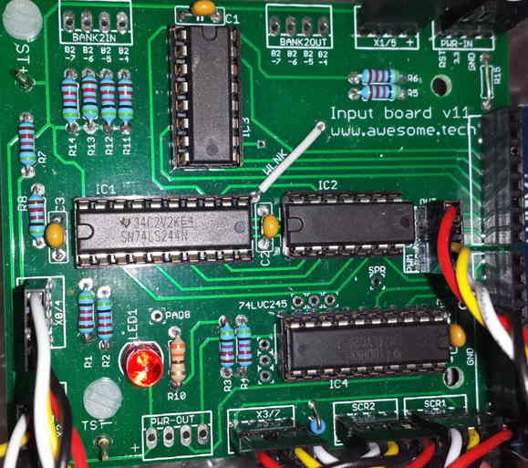
!! Solder the long Arduino pin connectors to the underside of the board (shown on RHS of photo), but don’t trim them !!
Insert IC’s when everything else completed.
Details
| PCB label | Value | Identifier | Notes |
| R1-R8 | 40k (40.2k used) | Yellow-Black-Red-Red_Brown | Pull down resistors ensure unconnected inputs aren’t floating |
| R9 | 300R | Orange-Black-Brown-Gold or Orange-Black-Black-Black-Brown | Sets LCD brightness |
| R10 | 300R | Orange-Black-Brown-Gold or Orange-Black-Black-Black-Brown | Sets LED brightness |
| R11-R14 | 40k (40.2k used) | Yellow-Black-Red-Red_Brown | Pull up resistors for usual case where Bank 2 is unused. |
| R15 | Use wire lead discarded from a previous component. | Optionally use resistor or diode to manage 3V level used for screen. | |
| WLINK | Use insulated wire link | ||
| C1, C2, C3, C4 | 0.1uF | 104 | Caps for IC’s |
| IC1 | 20 pin socket for 74LS244 | Solder to position, with orientation mark as per silk screen | |
| IC2 | 14 pin socket for 74LS02 | Solder to position, with orientation mark as per silk screen | |
| IC3 | 16 pin Socket for 74HC148 | Solder to position, with orientation mark as per silk screen | |
| IC4 | 20 pin Socket for 74LVC245 | Solder to position, with orientation mark as per silk screen | |
| X0/4 X1/5 X2/6 X3/7 PWR-IN OUT SCR1 SCR2 | 4 pin header | ||
| LED | 5mm RED LED | Note polarity – solder flat side as indicated on screen printed PCB. Power on indicator | |
| Edge pins/socket | Arduino Header Pins/Socket | !! Do not trim the leads, they are used to connect to the Arduino !! | |
| TST+ TST- | Single PCB pin | OPTIONAL Test pins for easy access to 5V and GND |
Install the IC’s
| IC1 | 74LS244 Note: you’ve been supplied with a 74LS244. Only the LS series has a schmitt trigger satisfactory for this circuit | 8 bit Schmitt trigger to convert analogue waveform into digital signal | |
| IC2 | 74LS02 | Quad NOR gate to combine A and B channels of each IRPS | |
| IC3 | 74HC148 | Encodes 8 input lines to 3 lines | |
| IC4 | 74LVC245 | Reduces 5V data bus to 3V for LCD screen |
Wire up
From the Wires bag, retrieve the bundle of 4 pin cables.
Install two cables to SCR1 and SCR2 header pins on the Input Board. Retrieve the Screen from the Input bag and carefully connect the two 4 pin connectors to the screen, such that the labels match on the back of the screen and the Input Board PCB – note there are slight differences in labels, but the pattern should be clear.
Connect another 4 pin cables to the various 4 pin headers on the Input Board. Note: follow a convention with wiring, eg. choose the brightest (lightest) colour of the 4 wires and assign it to the +ve volage as shown on the PCB.
The details table shows r9 is the same as r10.But in the picture r9 is blue and looks more like r1, not tan like r10. The picture confused us.
Hi Frank,
Tan coloured resistors are simply the traditional ‘old’ resistors with 4 band colour bands, and often with a gold band tolerance of 5%.
Blue metallic resistors are typically are increasingly common and have 5 band colour bands, often with a band tolerance of 1%.
In other words, don’t be worried if the overall resistor colour in the photo differs from your kit, just check the value is as indicated in the table, it’s handy to have a multimeter on hand to verify. Slight differences like this happen quite often with electronics projects (from other sellers too), as photos are often taken during the prototyping phase and very slight differences can occur with final parts kits because of reasons like pricing and availability.
Regards,
Dan