
Overview
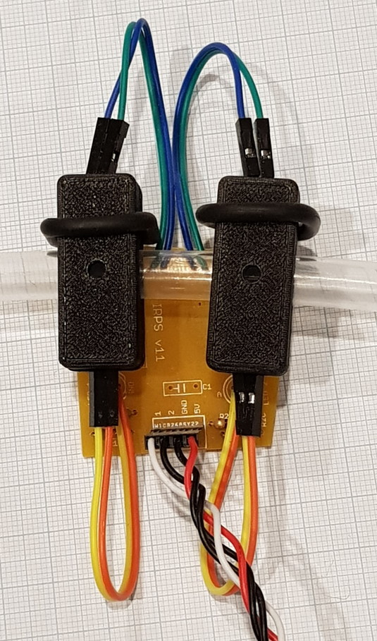
The IRPS unit is a dual photogate that senses the ball position via means of two infra-red transmitter/receiver pairs, aligned around the main tube by means of a 3d printed sensor housing. As the ball passes through the tube, it blocks the infra-red beam. The time difference between blocking signals, and known distance between the two transmitter/receiver pairs allows the Arduino to calculate ball speed. For design simplicity, a single half-shape housing is used four times, as top and bottom of each pair.
NOTE: the standard kit supports only 3 electromagnets and thus only requires 4 IRPS units (three for ongoing operation and one for high performance calibration).
Instructions
Work through the table below, soldering all components to the PCB. except for the LEDs and phototransistors.
| Component | Value | Identifier | Notes |
| R1A, R2A | 680R | Blue, gray, brown, gold. | Dropper Resistor on LED Anode |
| R1C, R2C | 33k | Orange, orange, orange, gold. | Collector Resistor for PhotoTransistor |
| 4 pin header connector | |||
| C1 | 10n | 104 | Optional Helps stabilise local supply voltage |
| Ribbon cable | Cut as indicated in text below | ||
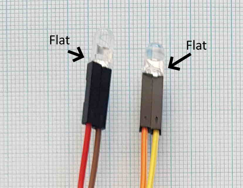
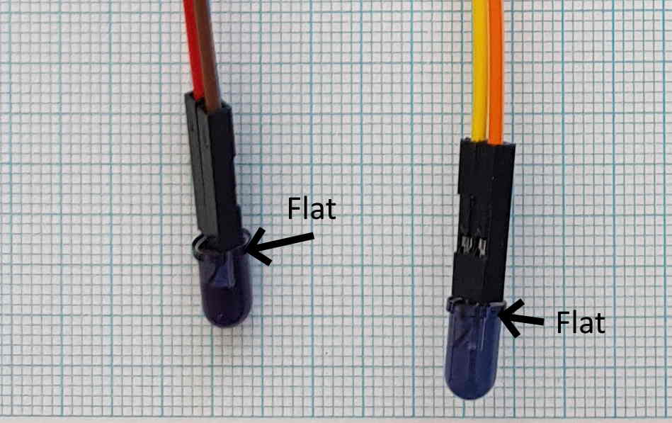
| IR LED1, LED2 | Dark colour | Infra-red LED Do not solder to board. Cut leads to 7mm and insert into sockets as shown. Note polarity. | |
| Phototransistor1, Phototransistor2 | Clear |
Infra-red phototransistor.
Do not solder to
board. Cut leads to 7mm and insert
into sockets as shown. Note polarity. |
Tear two-conductor strips of rainbow cable from the main group of ribbon cables, then cut in half.
Note carefully the two ‘C’ on the PCB indicating the Cathodes for the Phototransistors. Note carefully the two ‘A’ on the PCB indicating the Anodes for the LEDs. Note carefully: the IR LEDs have same PCB orientation, whereas the phototransistors orientation is symettrical.
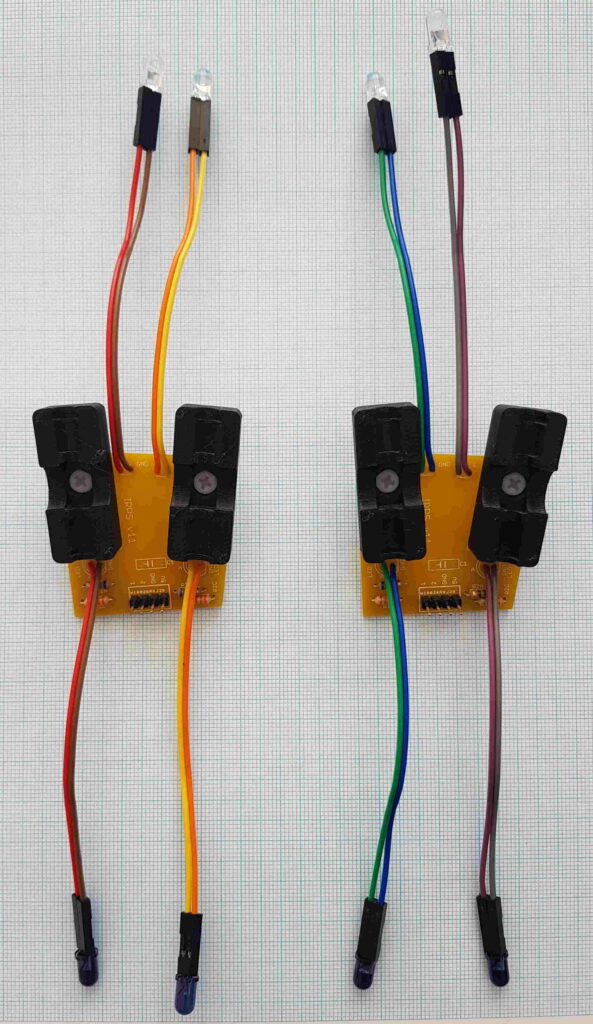
Use a color convention for the rainbow wiring to LEDs and Phototransistors: for example, use the lighter colour of the two conductors for the connection that is at a higher voltage. Eg. White is Anode, so it’s at a higher voltage than grey, which must be cathode. Similarly, the phototransistor collector is a lighter colour than the emitter.
Strip and solder the rainbow cable ends into the labelled pads on the PCB.
Once the wiring is in place, insert the Photo transistors and Photo diodes leads firmly into the rainbow cable sockets according to the polarity indications above.
Instructions don’t tell what hardware should be used to attach the shells to the PCBs.
Hi Thomas,
well spotted! For a standard size PPA it’s the 15mm screws (8 OFF), for a double size PPA it’s 16 OFF. And of course 8/16 OFF o-rings (all same size).
I’ll update the documentation.
Cheers
Dan
Have just updated the page https://awesometech1.wpengine.com/ppa-assembly-introduction/ which lists all the nuts and bolts required for each module.