
Overview
Each electromagnet converts electrical energy into a magnetic field, which accelerates the steel ball. The ferrite, laminations and ball form a magnetic circuit. In the same way that a ball rolls down an incline to minimise gravitational potential energy, a steel ball is attracted to the lowest state of magnetic potential energy in the centre of the coil.
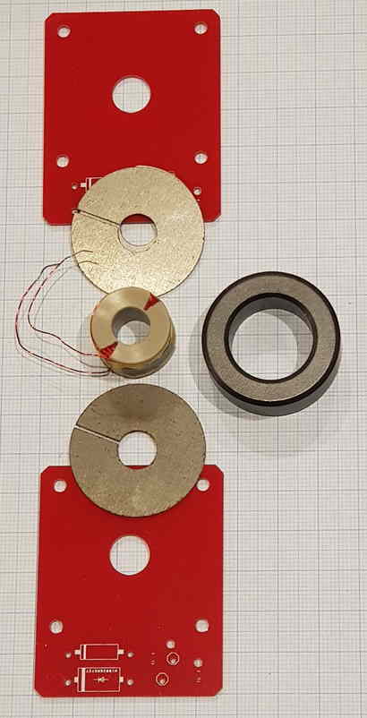
Each electromagnet consists of a pre-wound coil, surrounded by a ferrite toroid, and two steel laminations on each side, sandwiched between two red PCB’s secured by 25mm M3 screws with matching nuts.
This module also includes an assembly (yoke plus connecting rod) which connects the electromagnet and the IRPS, ensuring a constant distance between the two. Any variability between the two objects would reduce the performance of the timing calcuations.
Note this module’s mechanical assembly requires a high degree of dexterity to keep all the parts in required position during assembly.
Three electromagnets are included in the standard PPA kit, so repeat these instructions for each one. The Super PPA has six.
Electrical assembly
Orientation: The two red PCB’s are identical, it doesn’t matter which one is soldered to, but all components and connections must be on the same PCB.
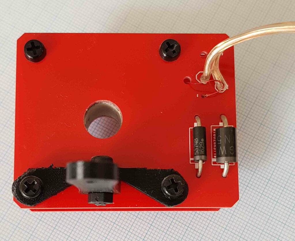
Solder diodes D1 and D2 in place.
| Component | Value | Identifier | Notes |
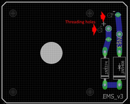
| D1 | 1N5374 The slimmer of the two diodes | Zener flyback diode to be positioned towards central hole. Note polarity: white band on diode to match PCB. | |
| D2 | 1N5408. Larger of the two diodes | Flyback Diode to be positioned towards edge of PCB. Note polarity: white band on diode to match PCB. |
For the standard PPA, cut the 68cm copper wire from the Wire bag with clear insulation into lengths around 16, 26 and 26cm. The lengths differ because the row of output terminals is not in the centre of the loop; some are closer than others.
For the Super PPA, cut the 275cm copper wire from the Wire bag with clear insulation into the lengths 35, 35, 50, 50, 50 and 50cm. The lengths differ because the row of output terminals is not in the centre of the loop; some are closer than others.
Wire specifications: the wire provided in the kit was https://www.jaycar.com.au/regular-duty-fig-8-speaker-cable-sold-per-metre/p/WB1704 . See the link’s specifications tab for full details.
Note that the EMS’ very low duty cycle means that almost any wire can be used.
Strip 5mm from each ends and tin with solder. Solder to the red PCB with diodes, with the white-striped wire going to the pad near the larger 1N5408 diode towards the edge of the PCB.
Yoke and arm assembly
To prepare for the main electromagnet assembly, bolt the connector rod to the yoke as shown with a 10mm M3 bolt. It is important to check the orientation is exactly the same as shown in the photos below.
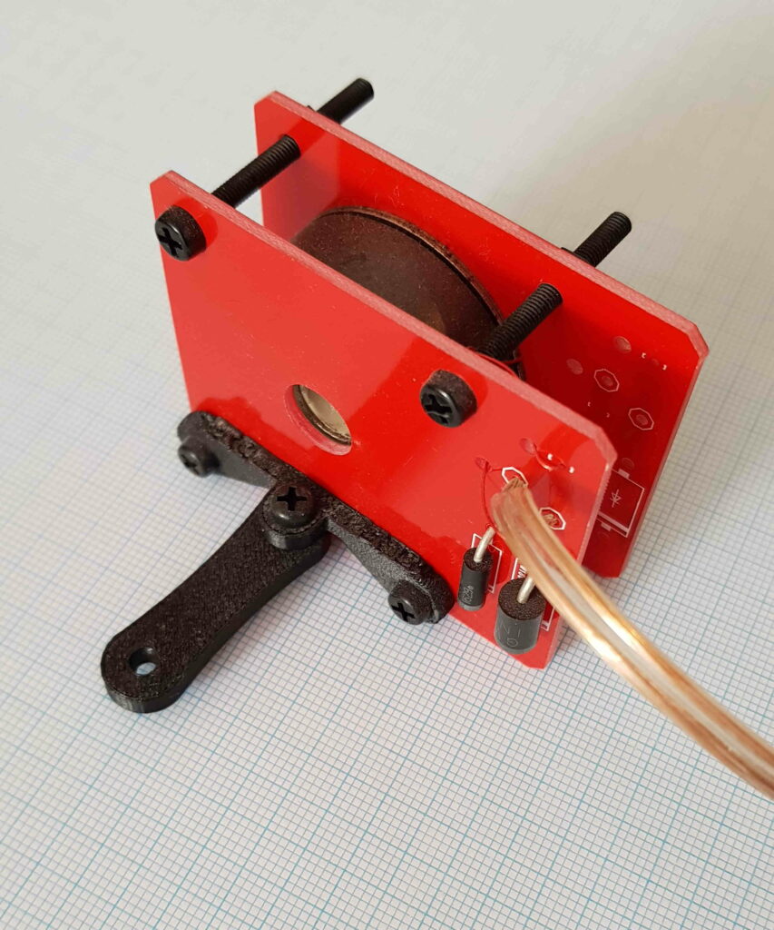
Electromagnet assembly
Ok, this is the hard bit, so take a deep breath. Read the instructions below fully before commencing.
Slide the pre-wound coil over the tube stub (from the Wire bag).
Position the ferrite around the pre-wound coil.
Cover each end of the pre wound coil with two laminations. Line up the lamination slots such that the wire passes through the slots at each side of the electromagnet.
Position the red PCB’s on each side of the laminations and hold the whole assembly between the fingers of one hand. With the other hand, position the yoke/arm assembly and thread the two nylon M3 bolts through the PCB holes. Tighten the two M3 nylon nuts in position, then repeat with the two remaining nylon M3 bolts and their nuts.
Final Electrical Connections
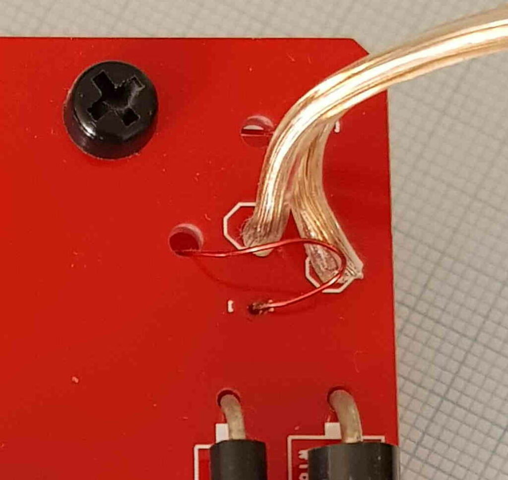
Carefully using needle nosed pliers or tweezers, take one of the enamelled coil leads and thread through the threading hole. Then loop it back to appear through the nearby soldering pad. Repeat for the other enamelled wire lead. Now solder the two enamelled copper wire leads, being careful to solder the part of the lead with the enamel stripped off.
I was only given 68cm of clear cable. I have a similar post back on the output board page about only getting 100cm of grey cable, needing 120.
Hi Phil, contact Dan via the dan@awesome.tech and he will sort you out. Cheers Paul
Hmm, just checked and the grey cable is too short as well – I think it should be 3x40cm, so 1.2m in total, but again the cable provided is too short at 97cm. Can you let me know what spec this cable is so I can locate some of that too please?
Thanks,
Paul H
Hi Paul, please contact Dan@awesome.tech and he gets it sorted out for you, Cheers, Paul
Hi All,
there was an error in the instructions – the provided wire length should be sufficient when you check the updated instructions. I’ve also added a link to the full specs for the wire, but noted that because of the low duty cycle, the wire choice is non-critical.
Cheers
Dan