Wiring different from examples
Quote from Jason Dulay on October 28, 2019, 7:22 pmHi, I just got an "upgraded" k40 that came with laser sight and an emergency stop button. I was excited to install my board but it seems different from all the examples ????
I'm a newbie and am pretty hesitant to mess around things, so help would be appreciated.
See attached.
Hi, I just got an "upgraded" k40 that came with laser sight and an emergency stop button. I was excited to install my board but it seems different from all the examples ????
I'm a newbie and am pretty hesitant to mess around things, so help would be appreciated.
See attached.
Uploaded files: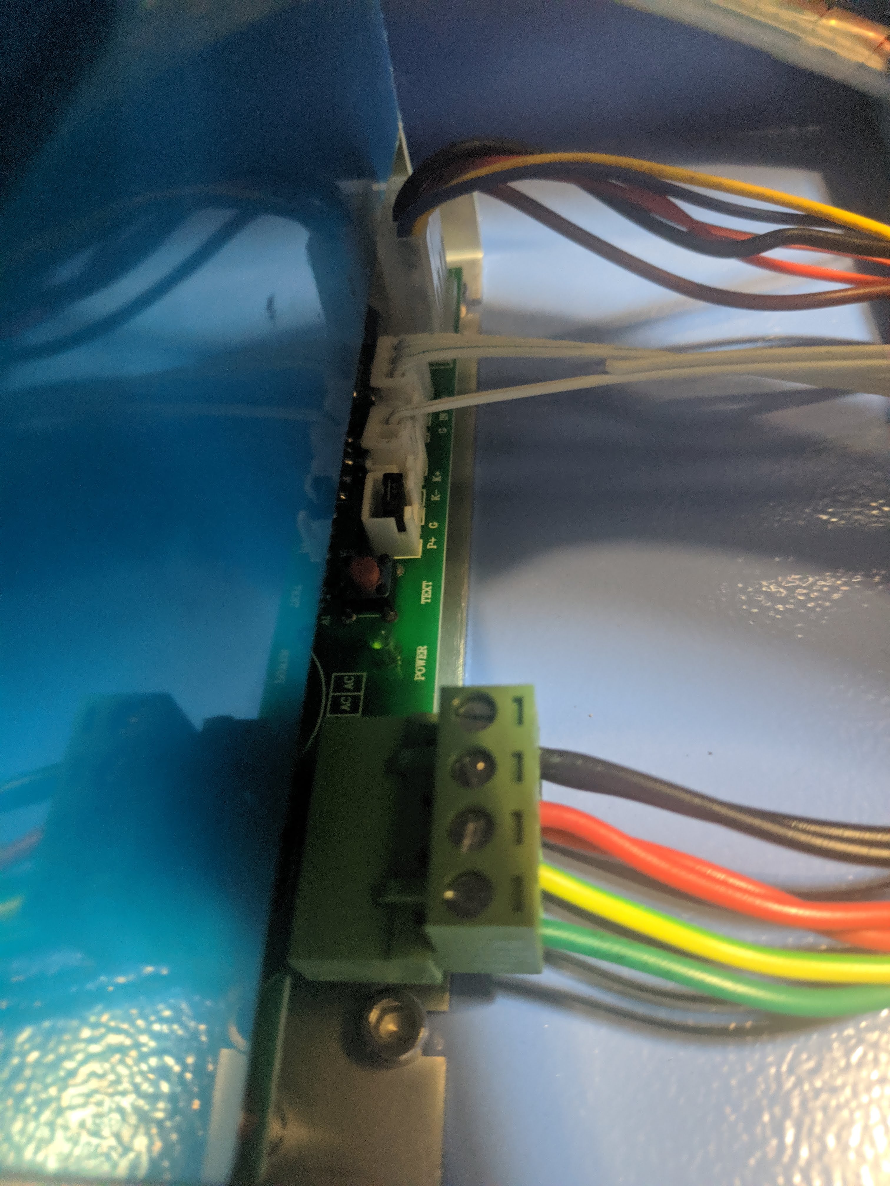
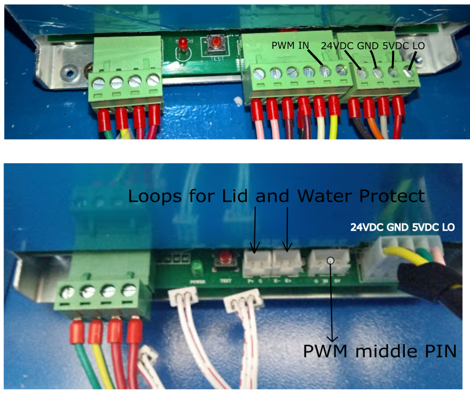
Quote from Paul on October 29, 2019, 11:56 amHi, the only difference is that the connectors for WP/LP (water protect loops) and IN (pwn in) are not terminal screw connectors but plugin connectors. So just follow the instructions, the silkscreen labels on the power supply are also the same.
See a photo below with the comparisons.
Hi, the only difference is that the connectors for WP/LP (water protect loops) and IN (pwn in) are not terminal screw connectors but plugin connectors. So just follow the instructions, the silkscreen labels on the power supply are also the same.
See a photo below with the comparisons.
Uploaded files:
Quote from Jason Dulay on October 30, 2019, 2:00 pmThanks Paul
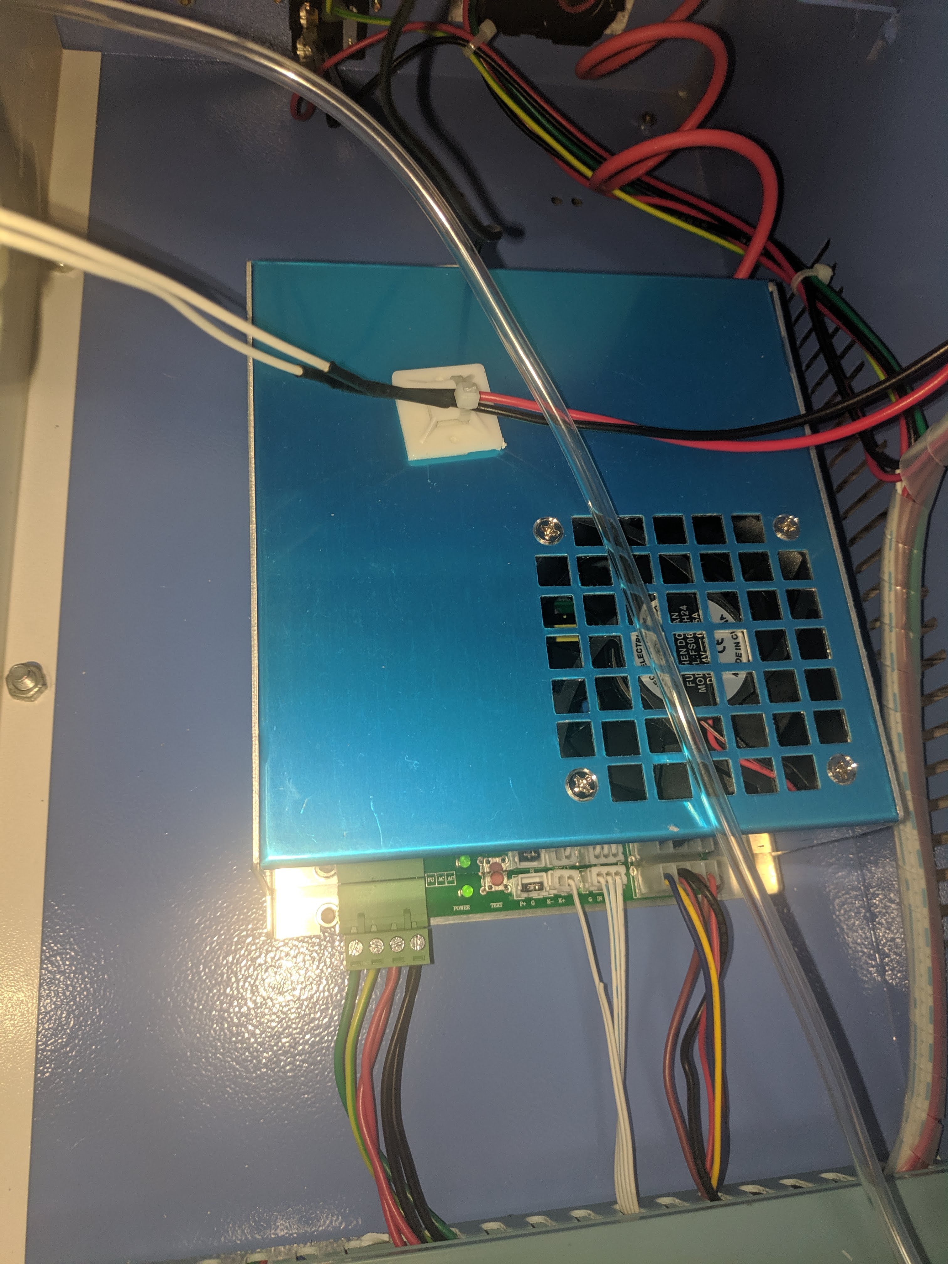
I have another issue. The board doesn't have a ribbon cable. See attached.
Thanks Paul
I have another issue. The board doesn't have a ribbon cable. See attached.
Uploaded files: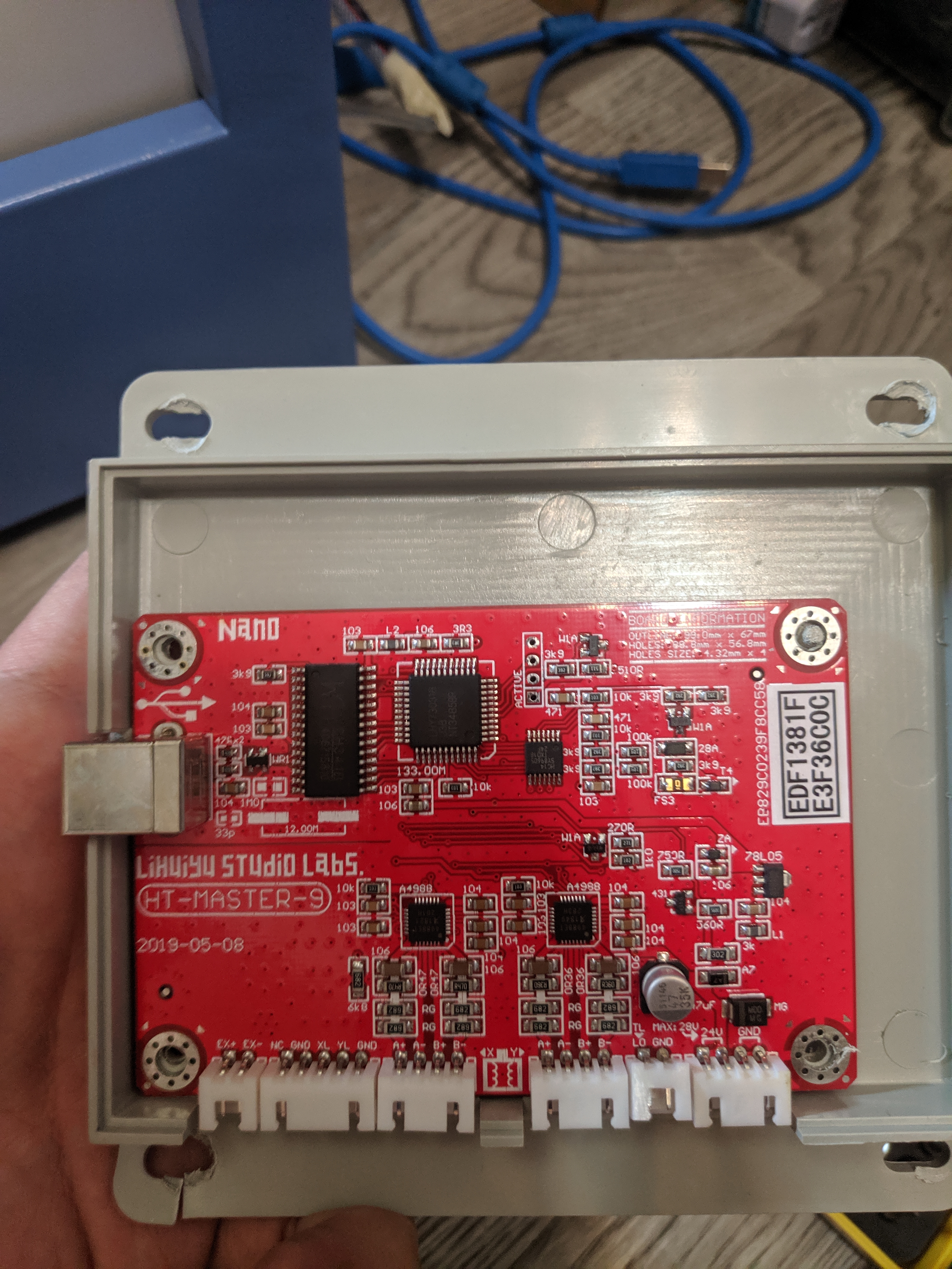
Quote from Jason Dulay on October 30, 2019, 3:08 pmOkay, I read through a bunch of posts and have something I want to try.
First of all, I realized that I need to buy a 4-pin power connector and splice my LO/GND/24V/GND cable into there. (Is this correct? The J3 socket doesn't have any labels on them)
Other than that, can I just 1:1 plug in the cables as per my attached diagram? No need for me to splice anything else or plug into the PSU?
Okay, I read through a bunch of posts and have something I want to try.
First of all, I realized that I need to buy a 4-pin power connector and splice my LO/GND/24V/GND cable into there. (Is this correct? The J3 socket doesn't have any labels on them)
Other than that, can I just 1:1 plug in the cables as per my attached diagram? No need for me to splice anything else or plug into the PSU?
Uploaded files:
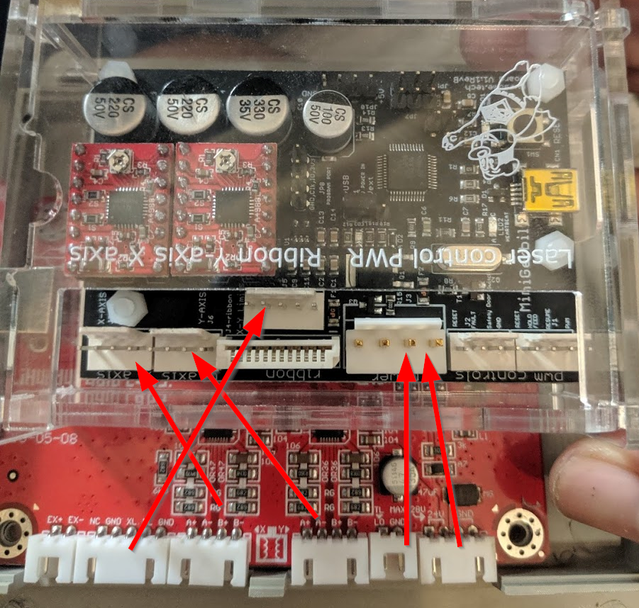
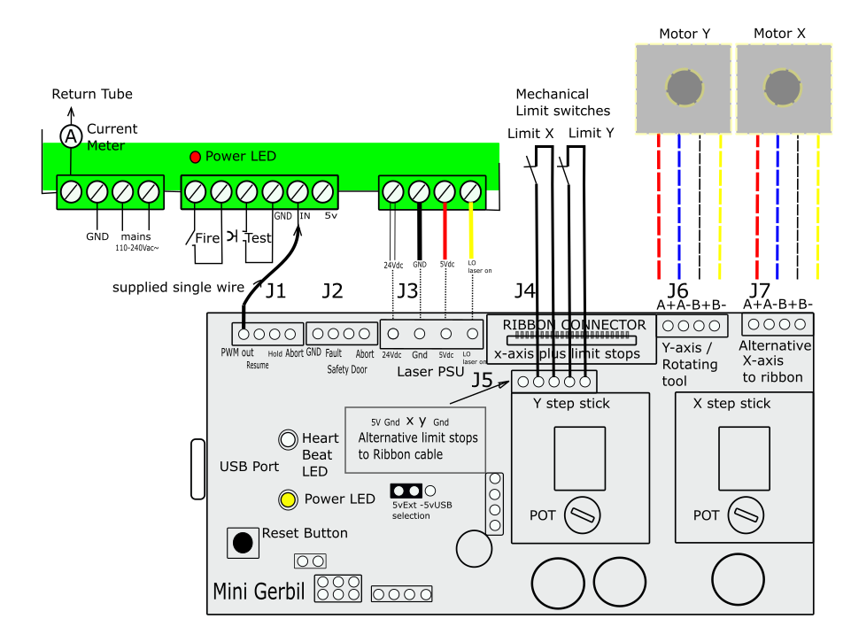
Quote from Paul on November 14, 2019, 12:09 pmYou need to wire the PWM output of the Mini Gerbil (first pin, of the first header on the right) to the IN screw terminal of the laser power supply.
The big connector connections are as below: LO, 5Vdc, Gnd, 24Vdc (as per your photo orientation)
You need to wire the PWM output of the Mini Gerbil (first pin, of the first header on the right) to the IN screw terminal of the laser power supply.
The big connector connections are as below: LO, 5Vdc, Gnd, 24Vdc (as per your photo orientation)
Uploaded files: