
Test button
Quote from Matthias Keila on January 17, 2021, 6:38 amHi there,
I would like to continue using the test button after installing the MG and add an additional three-way switch to switch between the pot and the MG. I am not very familiar with electronic circuit diagrams. That's why I painted it the way I understood it. Does it suit?
Another question: Is it enough to switch to use the test button, or does the macro described have to be called up in lightburn anyway?
Hi there,
I would like to continue using the test button after installing the MG and add an additional three-way switch to switch between the pot and the MG. I am not very familiar with electronic circuit diagrams. That's why I painted it the way I understood it. Does it suit?
Another question: Is it enough to switch to use the test button, or does the macro described have to be called up in lightburn anyway?
Uploaded files: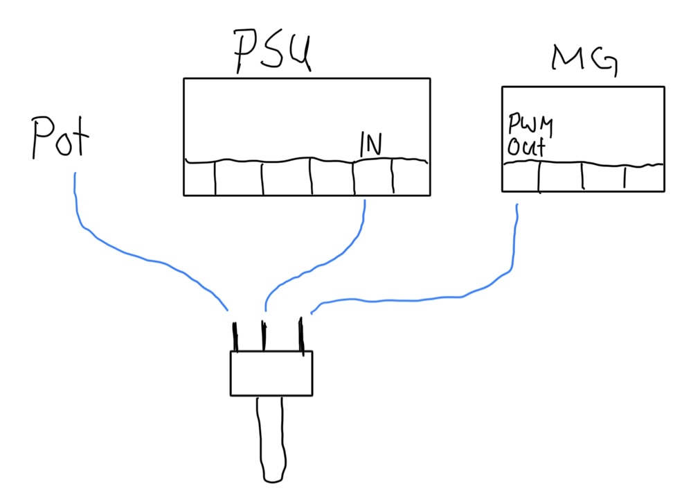
Quote from Paul on January 17, 2021, 11:00 amHi Matthias,
Thanks for asking, this is a complex setup. The purpose of the controller doing all the work via lightburn is a design philosophy. However there are two other setups.
A three way switch as described in your diagram is correct. However Lightburn does not switch off the LO signal during travel so you might get unintended faint lines when there is a bit of resistance in the Big power connector plug. The dev of Lightburn said to me that Lightburn want to use as minimal comms as possible because some basic controllers run on low baudrates (not the MG!) and it hampers the speed.
The purpose of the LightBurn macro is to switch on the LO signal so when you push the physical button, the K40 is lasering. So yes you need the macro in the above setup.
In order to use the test button and potmeter in a more predictive way, you should use a different method that does not use the LO (laser on or enable signal) anymore.
- You leave the potmeter connected to the IN connection. (as per original stock setup, no MG wires to this IN)
- You disconnect the LO wire at the PSU terminal block and use the PWM output wire from the MG instead.
Please let me know how it went,
cheers, Paul
Hi Matthias,
Thanks for asking, this is a complex setup. The purpose of the controller doing all the work via lightburn is a design philosophy. However there are two other setups.
A three way switch as described in your diagram is correct. However Lightburn does not switch off the LO signal during travel so you might get unintended faint lines when there is a bit of resistance in the Big power connector plug. The dev of Lightburn said to me that Lightburn want to use as minimal comms as possible because some basic controllers run on low baudrates (not the MG!) and it hampers the speed.
The purpose of the LightBurn macro is to switch on the LO signal so when you push the physical button, the K40 is lasering. So yes you need the macro in the above setup.
In order to use the test button and potmeter in a more predictive way, you should use a different method that does not use the LO (laser on or enable signal) anymore.
- You leave the potmeter connected to the IN connection. (as per original stock setup, no MG wires to this IN)
- You disconnect the LO wire at the PSU terminal block and use the PWM output wire from the MG instead.
Please let me know how it went,
cheers, Paul