
Problem with alternative EndStop
Quote from fforsito on September 13, 2019, 10:28 pmHello again 🙂
I am having trouble connecting alternative endstops, they would be the following:
https://es.aliexpress.com/item/32888904135.html?spm=a2g0s.9042311.0.0.274263c0piaXam
I connect them in the zone of alternative endstop and it does not matter how I connect them that in none detects them to me, I have also installed changing the configuration 5 of the GRBL from 1 to 0 but neither, I have fed the pin 5V externally also and nothing.
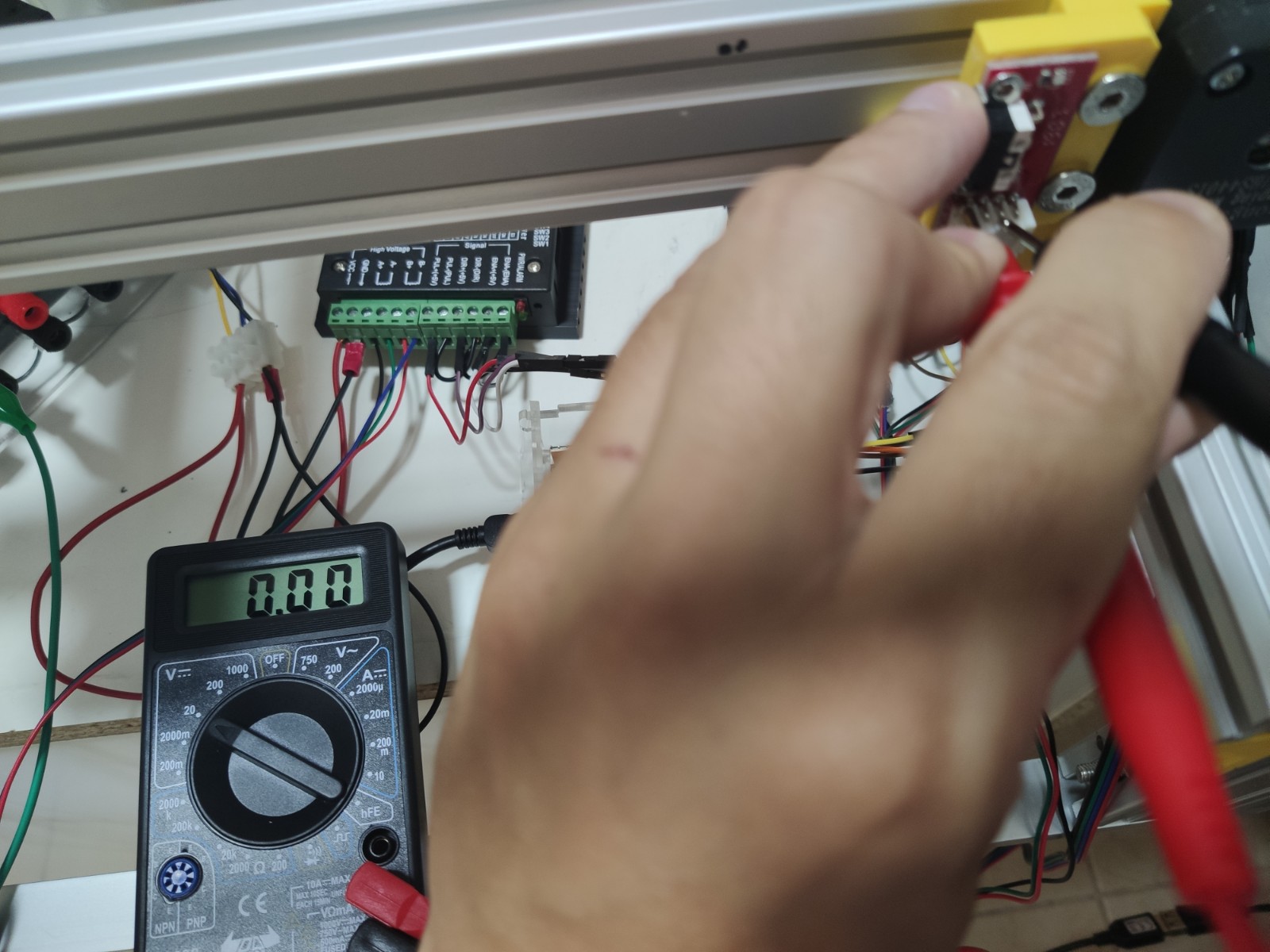
If I measure intensity when the axis is out it gives around 3.5V and if it is in the corner with the endstop pressed, it goes down to 0v so that enough current reaches it.
What should I be doing wrong?
I enclose measurements images
The NC and the Com do not work, and neither do NOT and COM, nor do you have any idea?
Edit:
I have also tried activating GRBL endstops at $ 21 = 1 but when I turn on the gerbil the alarm goes off and does not let me trigger anything and I must leave it again at 0.
I do not know what else to do
Hello again 🙂
I am having trouble connecting alternative endstops, they would be the following:
https://es.aliexpress.com/item/32888904135.html?spm=a2g0s.9042311.0.0.274263c0piaXam
I connect them in the zone of alternative endstop and it does not matter how I connect them that in none detects them to me, I have also installed changing the configuration 5 of the GRBL from 1 to 0 but neither, I have fed the pin 5V externally also and nothing.
If I measure intensity when the axis is out it gives around 3.5V and if it is in the corner with the endstop pressed, it goes down to 0v so that enough current reaches it.
What should I be doing wrong?
I enclose measurements images
The NC and the Com do not work, and neither do NOT and COM, nor do you have any idea?
Edit:
I have also tried activating GRBL endstops at $ 21 = 1 but when I turn on the gerbil the alarm goes off and does not let me trigger anything and I must leave it again at 0.
I do not know what else to do
Uploaded files: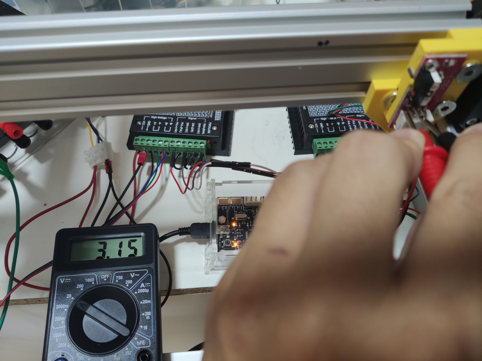
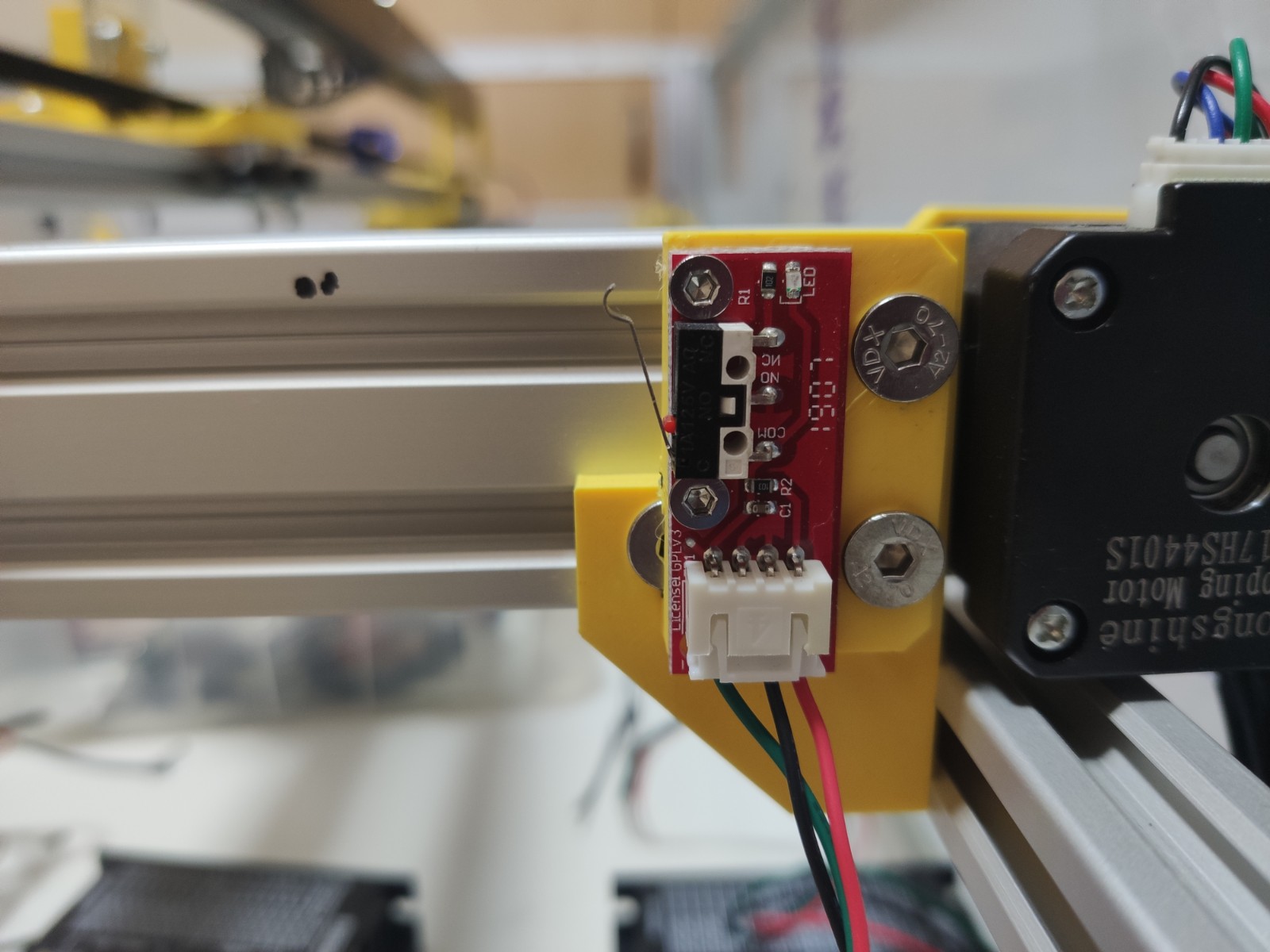
Quote from Paul on September 14, 2019, 9:20 amHi, the issue with these endstops is that they need 5V to feed the LEDs on it and there is a resistor in series that causes the issue. You can jumper the switch connections - NC and COM (or GND) to the connector on the small PCB. (like 1 cm leads).
This turns it truly into a mechanical switch. You just use the NC, normally closed and COM, common pins of the switch. Use a multi-meter to verify the functioning.
Let me know if you have more questions
Hi, the issue with these endstops is that they need 5V to feed the LEDs on it and there is a resistor in series that causes the issue. You can jumper the switch connections - NC and COM (or GND) to the connector on the small PCB. (like 1 cm leads).
This turns it truly into a mechanical switch. You just use the NC, normally closed and COM, common pins of the switch. Use a multi-meter to verify the functioning.
Let me know if you have more questions
Quote from fforsito on September 14, 2019, 9:33 amQuote from Paul DeGroot on September 14, 2019, 9:20 amHi, the issue with these endstops is that they need 5V to feed the LEDs on it and there is a resistor in series that causes the issue. You can jumper the switch connections - NC and COM (or GND) to the connector on the small PCB. (like 1 cm leads).
This turns it truly into a mechanical switch. You just use the NC, normally closed and COM, common pins of the switch. Use a multi-meter to verify the functioning.
Let me know if you have more questions
Thanks Paul.
You mean a bridge like the one in the picture?
Quote from Paul DeGroot on September 14, 2019, 9:20 amHi, the issue with these endstops is that they need 5V to feed the LEDs on it and there is a resistor in series that causes the issue. You can jumper the switch connections - NC and COM (or GND) to the connector on the small PCB. (like 1 cm leads).
This turns it truly into a mechanical switch. You just use the NC, normally closed and COM, common pins of the switch. Use a multi-meter to verify the functioning.
Let me know if you have more questions
Thanks Paul.
You mean a bridge like the one in the picture?
Uploaded files: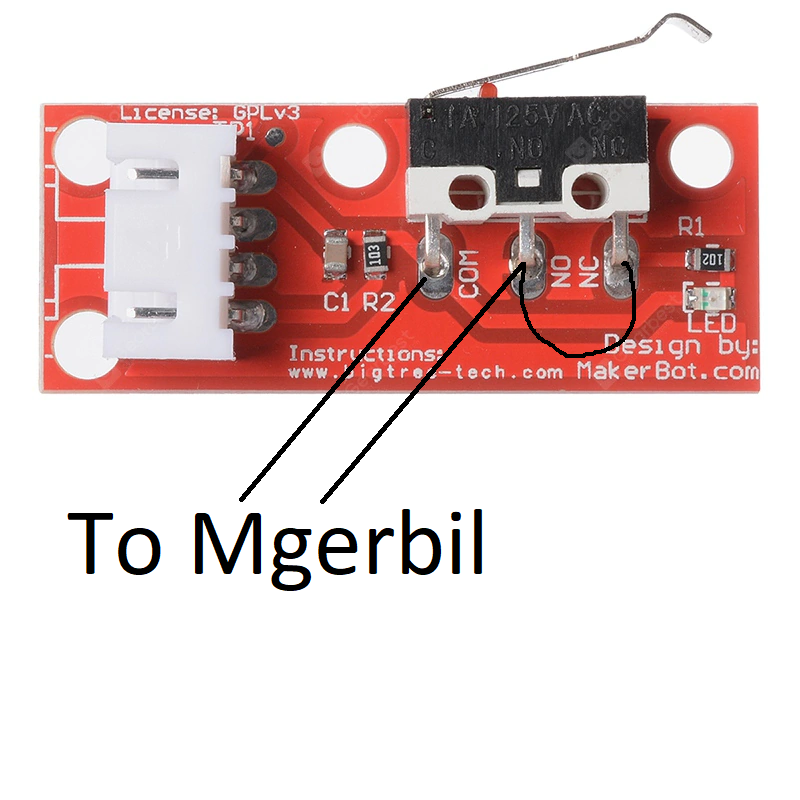
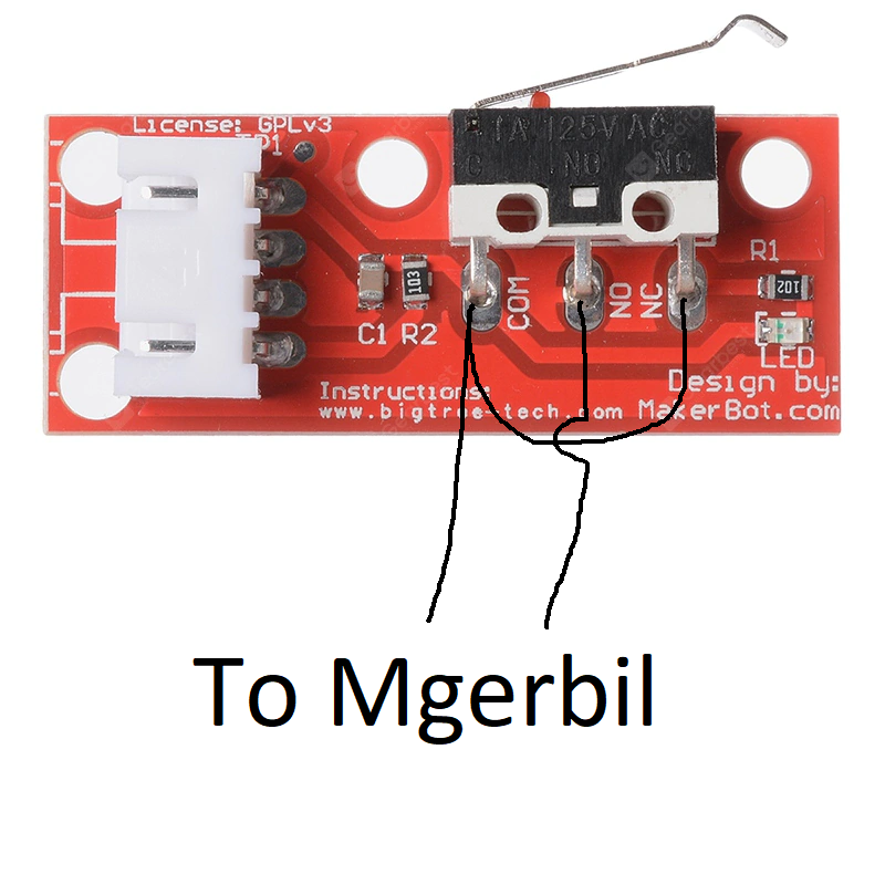
Quote from Paul on September 14, 2019, 12:26 pmFirst picture should work but don't bridge NO and NC. Just use NC and COM or NO and COM (you need to invert the limits when using NO).
NO=Normally open, NC=Normally closed, They share the common COM.
First picture should work but don't bridge NO and NC. Just use NC and COM or NO and COM (you need to invert the limits when using NO).
NO=Normally open, NC=Normally closed, They share the common COM.
Quote from fforsito on September 14, 2019, 8:51 pmQuote from Paul DeGroot on September 14, 2019, 12:26 pmFirst picture should work but don't bridge NO and NC. Just use NC and COM or NO and COM (you need to invert the limits when using NO).
NO=Normally open, NC=Normally closed, They share the common COM.
This is how I did it and Paul doesn't work, neither using NC and COM nor using NO and COM, that's why I doubt that they don't work but if the voltage comes to them.
Should I activate something in grbl for alternate limit switches?
Quote from Paul DeGroot on September 14, 2019, 12:26 pmFirst picture should work but don't bridge NO and NC. Just use NC and COM or NO and COM (you need to invert the limits when using NO).
NO=Normally open, NC=Normally closed, They share the common COM.
This is how I did it and Paul doesn't work, neither using NC and COM nor using NO and COM, that's why I doubt that they don't work but if the voltage comes to them.
Should I activate something in grbl for alternate limit switches?
Quote from fforsito on September 14, 2019, 9:07 pmPaul, it seems that I have already found the fault.
The following must be changed in GRBL:
$ 5 Change from 1 to 0 (Invert limit pins, boolean)
$ 21 Change from 0 to 1 (Hard limits enable, boolean)Now it works without problems .... I'll keep telling if I see something weird
The only thing is that when you turn on the machine you must do Home forced to unlock
🙂
Paul, it seems that I have already found the fault.
The following must be changed in GRBL:
$ 5 Change from 1 to 0 (Invert limit pins, boolean)
$ 21 Change from 0 to 1 (Hard limits enable, boolean)
Now it works without problems .... I'll keep telling if I see something weird
The only thing is that when you turn on the machine you must do Home forced to unlock
🙂
Quote from Paul on September 15, 2019, 9:16 amHi, glad you worked it all out, well done! Homing is necessary because there are no encoders to tell the controller where the gantry is on start up.
Hi, glad you worked it all out, well done! Homing is necessary because there are no encoders to tell the controller where the gantry is on start up.