
Photo's of the drag chain installed
Quote from Paul on May 6, 2018, 7:33 pmFor some people it has been difficult to understand how to install the drag chain. One even rebuild the entire drag chain solution because he could not understand how to install it (what a shame and lost time/effort).
The video is here https://youtu.be/D2wtJ8JVxko
For some people it has been difficult to understand how to install the drag chain. One even rebuild the entire drag chain solution because he could not understand how to install it (what a shame and lost time/effort).
The video is here https://youtu.be/D2wtJ8JVxko
Uploaded files:
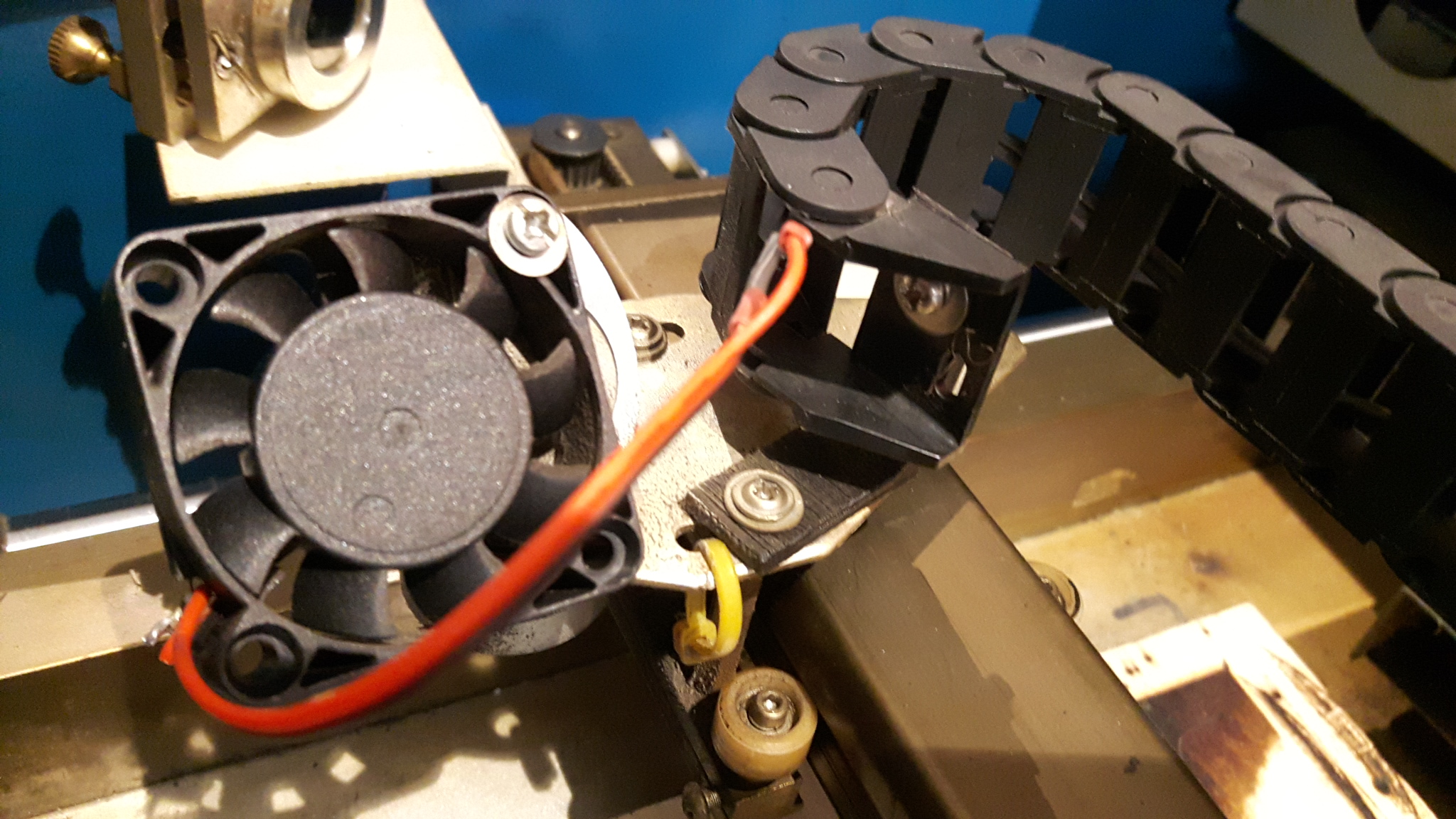
Quote from Paul on May 6, 2018, 7:38 pmthe photo's are taken from the front of the k40. Access to the 2 allen screw is via the panel hole (some have a light there).
The laser head end:
The fan uses the long m4 thru the lens clip. The L shape bracket uses the existing hole in the foot plate. The chain folds into the front of the L bracket.
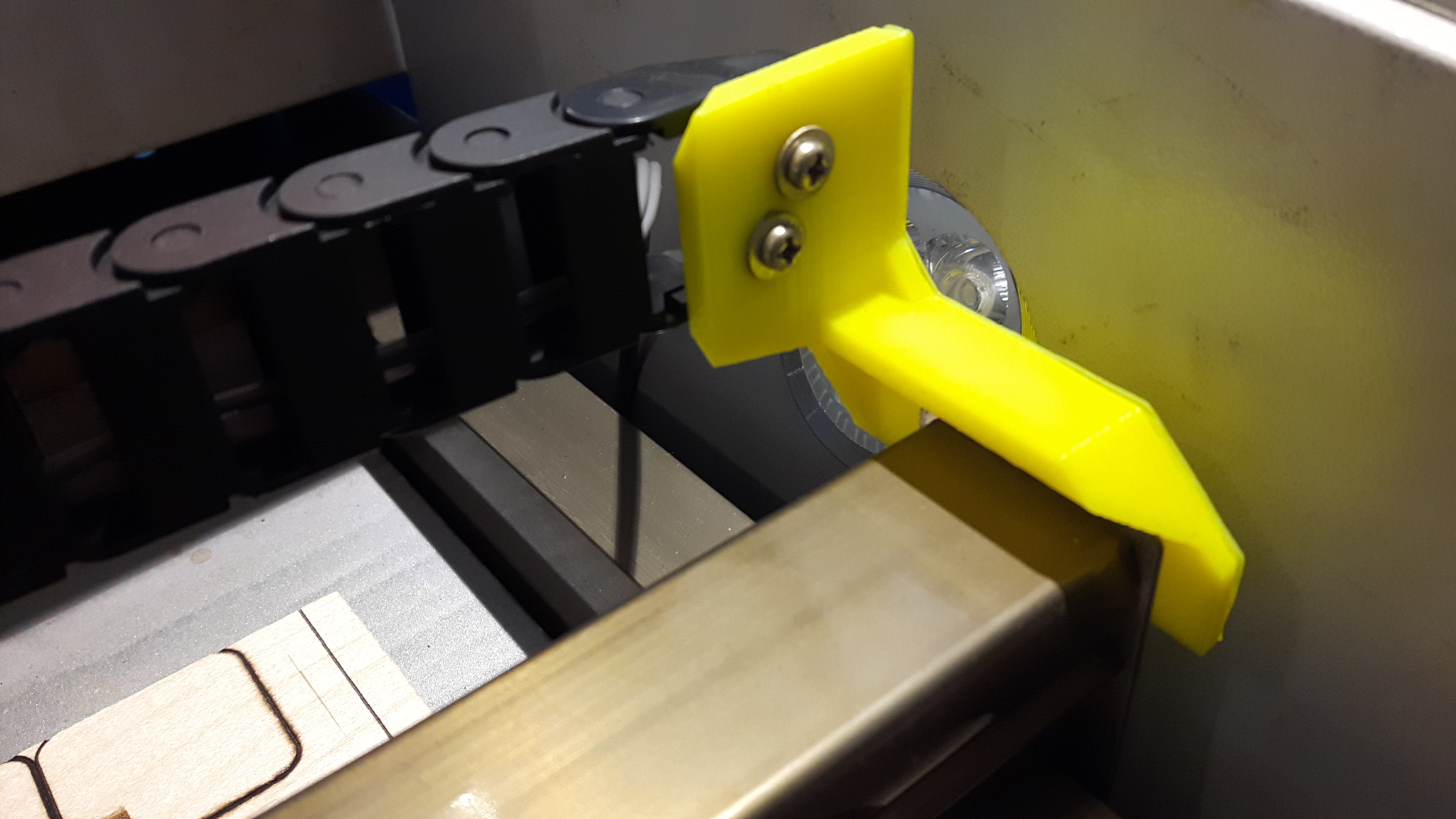
The bar end:
The chain is connected behind the bracket.
the photo's are taken from the front of the k40. Access to the 2 allen screw is via the panel hole (some have a light there).
The laser head end:
The fan uses the long m4 thru the lens clip. The L shape bracket uses the existing hole in the foot plate. The chain folds into the front of the L bracket.
The bar end:
The chain is connected behind the bracket.
Quote from Paul on May 10, 2019, 10:07 amNote that both ends of the drag chain are different. If the holes don't match then you have the wrong end of the drag chain. BTW I pre-assemble the drag chain with the brackets to avoid misunderstanding. Just align and tighten the screws.
Note that both ends of the drag chain are different. If the holes don't match then you have the wrong end of the drag chain. BTW I pre-assemble the drag chain with the brackets to avoid misunderstanding. Just align and tighten the screws.
Quote from mathiaspl20 on July 31, 2019, 9:55 ambetter solution: Slightly longer drag chain mounted to the back wall. Temporary solution, it is just hot-glued in place atm, but you could easily affix it with screws. Lying axial fan on the laser head with an adjustable duct, again, temporary. Ill be running a hose through the drag chain to supply air form a remote 2 stage fan assembly in the psu section. chain works well, but i'll have to move the end on the laser head end of the drag chain to allow the chain to bend back earlier to make sure not to ever cross the laser beam. "fixed" for now by homing in top right corner.
better solution: Slightly longer drag chain mounted to the back wall. Temporary solution, it is just hot-glued in place atm, but you could easily affix it with screws. Lying axial fan on the laser head with an adjustable duct, again, temporary. Ill be running a hose through the drag chain to supply air form a remote 2 stage fan assembly in the psu section. chain works well, but i'll have to move the end on the laser head end of the drag chain to allow the chain to bend back earlier to make sure not to ever cross the laser beam. "fixed" for now by homing in top right corner.
Uploaded files: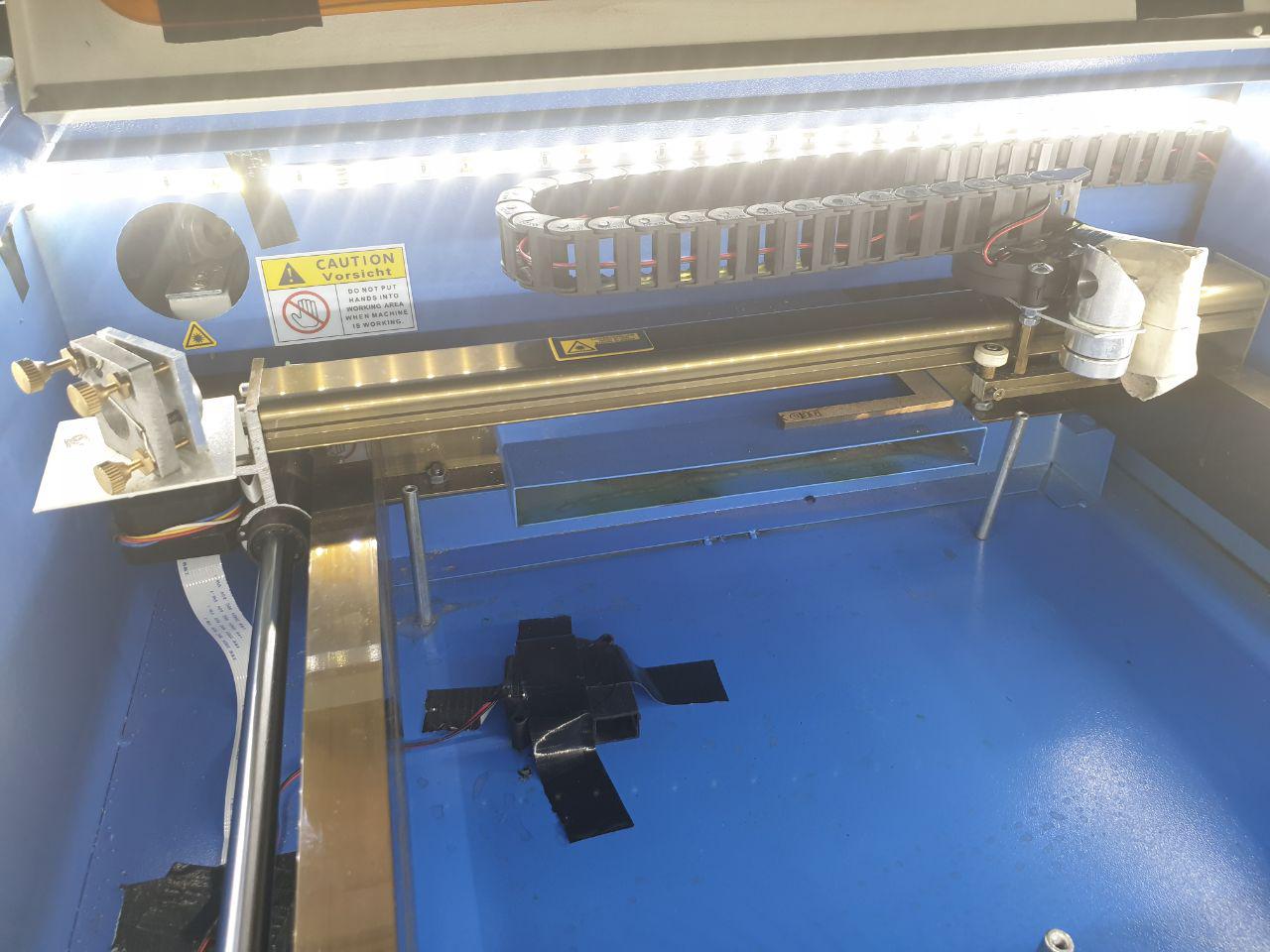
Quote from Paul on July 31, 2019, 1:13 pmBeautiful Matthias, I love it when people come up with new ideas and solution. Well done!
Beautiful Matthias, I love it when people come up with new ideas and solution. Well done!
Quote from Philip Peterman on September 9, 2019, 12:13 amMy problem is that when installed as directed the bar end mount prevents the gantry from engaging the y-axis end stop. I think I'll try Mathias' solution and mount it to the back of the case.
My problem is that when installed as directed the bar end mount prevents the gantry from engaging the y-axis end stop. I think I'll try Mathias' solution and mount it to the back of the case.
Quote from Philip Peterman on September 9, 2019, 1:25 amactually ended up just pulling out the calipers and the drill press. Works like a charm now.
actually ended up just pulling out the calipers and the drill press. Works like a charm now.
Quote from Keith Ealanta on December 3, 2024, 12:26 pmThanks for the suggestion mathiaspl20.
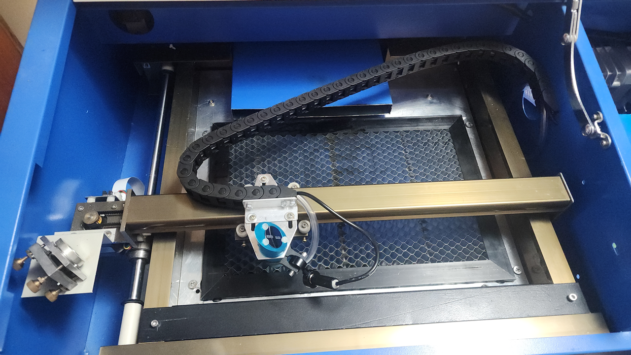
To reduce the amount the chain pushed into the laser path, I mounted it on the right side wall.,
This way, when the head is at the two left most corners (front and rear), the chain is at it's shortest and doesn't get in the way, and at the mid left there is less chain than is required for a rear-wall install and it has space to curve so it's not pressed into the beam-path.
So again, thanks for the suggestion.
Oh, and the mistake with where i put it? It's in the way of the hinge. The hinge has enough slack to go around it, but it frequently catches. - When I get a moment I'll 3d print a cover that will push the catch outward and that will sort it completely.
Thanks for the suggestion mathiaspl20.
To reduce the amount the chain pushed into the laser path, I mounted it on the right side wall.,
This way, when the head is at the two left most corners (front and rear), the chain is at it's shortest and doesn't get in the way, and at the mid left there is less chain than is required for a rear-wall install and it has space to curve so it's not pressed into the beam-path.
So again, thanks for the suggestion.
Oh, and the mistake with where i put it? It's in the way of the hinge. The hinge has enough slack to go around it, but it frequently catches. - When I get a moment I'll 3d print a cover that will push the catch outward and that will sort it completely.
Quote from Paul on December 3, 2024, 1:48 pmHumm, when the mount end it's on the gantry bar end (right side/not the lens side left) than it should be free to move. Well, if yours work then it is fine too. You can shorten the white tubes on the Y axis rod's ends, so it gives you more room and also more work space in the Y direction. Next is to remove or shorten the blue exhaust part in the middle/back of the machine. It doesn't really help much have it sticking so far into the work space. Add a little PC fan to the lens carrier or air assist. Both help to remove the smoke and sooth going to the lens. Good luck!
Humm, when the mount end it's on the gantry bar end (right side/not the lens side left) than it should be free to move. Well, if yours work then it is fine too. You can shorten the white tubes on the Y axis rod's ends, so it gives you more room and also more work space in the Y direction. Next is to remove or shorten the blue exhaust part in the middle/back of the machine. It doesn't really help much have it sticking so far into the work space. Add a little PC fan to the lens carrier or air assist. Both help to remove the smoke and sooth going to the lens. Good luck!
Quote from Keith Ealanta on December 5, 2024, 10:07 amThanks for the thoughts - You can see the air assist tube in the pic, so that one is sorted.
The air intake has been trimmed already - the laser misses by 1.5mm :). The white tubes are stopping the laser less than 1mm before the cover panel over the drive rod on the end, so not much point in another mm or two. For now I'll probably stop once I finish getting the switch on the air-assist working, and try to use this enough to justify buying a bigger and better model. (It's basically an A4 40W - I'd like to step up to a pass-through 100W+ able to take 1800x900mm)Changes from original...
New lenses and mirrors
Air Assist
Sighting laser with front-panel toggle button
Adjustable honeycomb support plate
Improved plugs for external pumps and fans. (I'm in Australia, so now using IEC60320 - C13 plugs)
Trimmed Air outlet
Thanks for the thoughts - You can see the air assist tube in the pic, so that one is sorted.
The air intake has been trimmed already - the laser misses by 1.5mm :). The white tubes are stopping the laser less than 1mm before the cover panel over the drive rod on the end, so not much point in another mm or two. For now I'll probably stop once I finish getting the switch on the air-assist working, and try to use this enough to justify buying a bigger and better model. (It's basically an A4 40W - I'd like to step up to a pass-through 100W+ able to take 1800x900mm)
Changes from original...
New lenses and mirrors
Air Assist
Sighting laser with front-panel toggle button
Adjustable honeycomb support plate
Improved plugs for external pumps and fans. (I'm in Australia, so now using IEC60320 - C13 plugs)
Trimmed Air outlet
Quote from Keith Ealanta on December 5, 2024, 10:22 amActually, Paul, any tips for zero-width limit switches? I'd like limit switches, but I don't want to lose even a mm to get it.
Actually, Paul, any tips for zero-width limit switches? I'd like limit switches, but I don't want to lose even a mm to get it.
Quote from Paul on December 5, 2024, 1:45 pmBasically you need TMC stepsticks for zero limit switches. They use firmware to detect a stalled motor.
Best is to stick with the opto switches. There hysteris distance is pretty small. You can use trial and error to find the smallest distance by editing $27 command e.g. $27=2 where 2 is 2mm.
Basically you need TMC stepsticks for zero limit switches. They use firmware to detect a stalled motor.
Best is to stick with the opto switches. There hysteris distance is pretty small. You can use trial and error to find the smallest distance by editing $27 command e.g. $27=2 where 2 is 2mm.
Quote from Keith Ealanta on March 27, 2025, 2:28 pmQuote from Paul on December 3, 2024, 1:48 pmHumm, when the mount end it's on the gantry bar end (right side/not the lens side left) than it should be free to move.
I just wanted to post a follow-up on this one - There may be some further cleverness being assumed that I'm not familiar with so apologies if I'm missing something. It seems to me that having the drag-chain end attached to the gantry means that you have a pipe being dragged forward and back as the gantry moves - it keeps everything out of the way in the cutting area, but puts more strain/wear on the pipes/cables before they enter the chain. By attaching to the frame at the right location, the drag-chain works for both X and Y components of movement, keeping one end static to the machine, and the other static to the head. Everything flexes inside the chain but outside everything is static.
I don't know how important this is, but to me, it feels much more stable, secure, and controlled.
I
Quote from Paul on December 3, 2024, 1:48 pmHumm, when the mount end it's on the gantry bar end (right side/not the lens side left) than it should be free to move.
I just wanted to post a follow-up on this one - There may be some further cleverness being assumed that I'm not familiar with so apologies if I'm missing something. It seems to me that having the drag-chain end attached to the gantry means that you have a pipe being dragged forward and back as the gantry moves - it keeps everything out of the way in the cutting area, but puts more strain/wear on the pipes/cables before they enter the chain. By attaching to the frame at the right location, the drag-chain works for both X and Y components of movement, keeping one end static to the machine, and the other static to the head. Everything flexes inside the chain but outside everything is static.
I don't know how important this is, but to me, it feels much more stable, secure, and controlled.
I
Quote from Paul on March 28, 2025, 12:13 pmDrag chains are use for cable management, in other words, cable don't get in the way of the moving parts. The disadvantage is indeed that the gantry will encounter more resistance to move freely. The movement on the K40 is very slow in comparison to the professional laser engravers so it won't effect the engraving speed. Some people use curled snake cables as an alternative. Enjoy!
Drag chains are use for cable management, in other words, cable don't get in the way of the moving parts. The disadvantage is indeed that the gantry will encounter more resistance to move freely. The movement on the K40 is very slow in comparison to the professional laser engravers so it won't effect the engraving speed. Some people use curled snake cables as an alternative. Enjoy!