
Etching leaving Profile Marks (Ghosting) and Traverse Lines
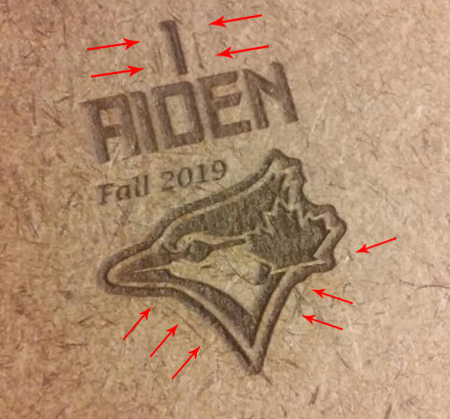
Quote from Dbtoutfit on October 20, 2019, 1:49 amAs you can see in the pic I am getting a profile at the edges where the over scan max is.
What causes this?
I have also seen sometimes between cuts where the rapid/traverse moves have a faint line as if the laser isn’t fulling turning off between cuts. Feeling like they are both related.TIA
73143004_2390232531251587_16681910675701760_n.jpg1613×1619 257 KB$0=5
$1=255
$2=0
$3=1
$4=0
$5=1
$6=0
$7=0
(ATC M6, pulse/ff)
$8=100
(ATC Tool Td, milliseconds)
$9=100
(ATC M6 Td, milliseconds)
$10=31
$11=0.010
$12=0.002
$13=0
$19=0
(Softstart, milliseconds)
$20=0
$21=0
$22=1
$23=3
$24=10000.000
$25=5000.000
$26=136
$27=1.000
$28=11
(Spindle freq. 0 to 15)
$30=800
$31=0
$32=1
$100=158.395
(x:stp/mm)
$101=157.583
(y:stp/mm)
$102=160.000
(z:stp/mm)
$103=160.000
(a:stp/mm)
$104=160.000
(b:stp/mm)
$110=13000.000
(x:mm/min)
$111=5000.000
(y:mm/min)
$112=5000.000
(z:mm/min)
$113=5000.000
(a:mm/min)
$114=5000.000
(b:mm/min)
$120=7000.000
(x:mm/s^2)
$121=1500.000
(y:mm/s^2)
$122=5000.000
(z:mm/s^2)
$123=3000.000
(a:mm/s^2)
$124=3000.000
(b:mm/s^2)
$130=230.000
(x:mm max)
$131=320.000
(y:mm max)
$132=200.000
(z:mm max)
$133=200.000
(a:mm max)
$134=200.000
(b:mm max)
As you can see in the pic I am getting a profile at the edges where the over scan max is.
What causes this?
I have also seen sometimes between cuts where the rapid/traverse moves have a faint line as if the laser isn’t fulling turning off between cuts. Feeling like they are both related.
TIA
$0=5
$1=255
$2=0
$3=1
$4=0
$5=1
$6=0
$7=0
(ATC M6, pulse/ff)
$8=100
(ATC Tool Td, milliseconds)
$9=100
(ATC M6 Td, milliseconds)
$10=31
$11=0.010
$12=0.002
$13=0
$19=0
(Softstart, milliseconds)
$20=0
$21=0
$22=1
$23=3
$24=10000.000
$25=5000.000
$26=136
$27=1.000
$28=11
(Spindle freq. 0 to 15)
$30=800
$31=0
$32=1
$100=158.395
(x:stp/mm)
$101=157.583
(y:stp/mm)
$102=160.000
(z:stp/mm)
$103=160.000
(a:stp/mm)
$104=160.000
(b:stp/mm)
$110=13000.000
(x:mm/min)
$111=5000.000
(y:mm/min)
$112=5000.000
(z:mm/min)
$113=5000.000
(a:mm/min)
$114=5000.000
(b:mm/min)
$120=7000.000
(x:mm/s^2)
$121=1500.000
(y:mm/s^2)
$122=5000.000
(z:mm/s^2)
$123=3000.000
(a:mm/s^2)
$124=3000.000
(b:mm/s^2)
$130=230.000
(x:mm max)
$131=320.000
(y:mm max)
$132=200.000
(z:mm max)
$133=200.000
(a:mm max)
$134=200.000
(b:mm max)
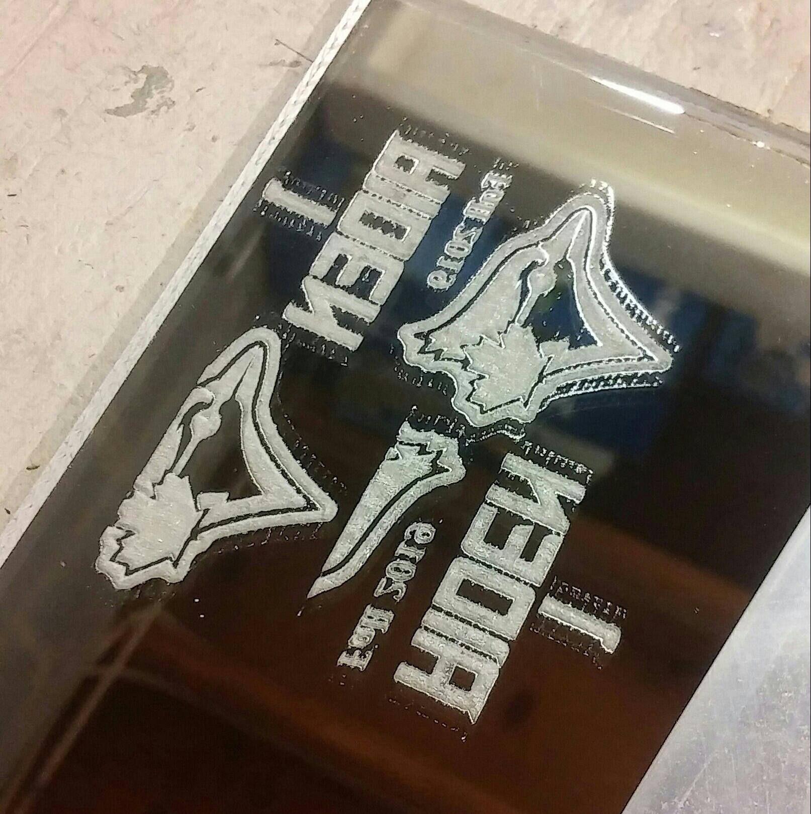
Quote from Dbtoutfit on October 20, 2019, 7:01 amSo looks like I found the culprit.
I just finished my new 48x48 CNC Router build and learned a lot about EMI using a Spindle and VFD on this build, that got me thinking about my laser wiring…
I moved some wires and the MiniG around (power off) and on the next test it was worse so I knew I was on to something.When I did the MiniG upgrade I removed all the spiral wire wrap due to all the needed rewiring but never installed it back.
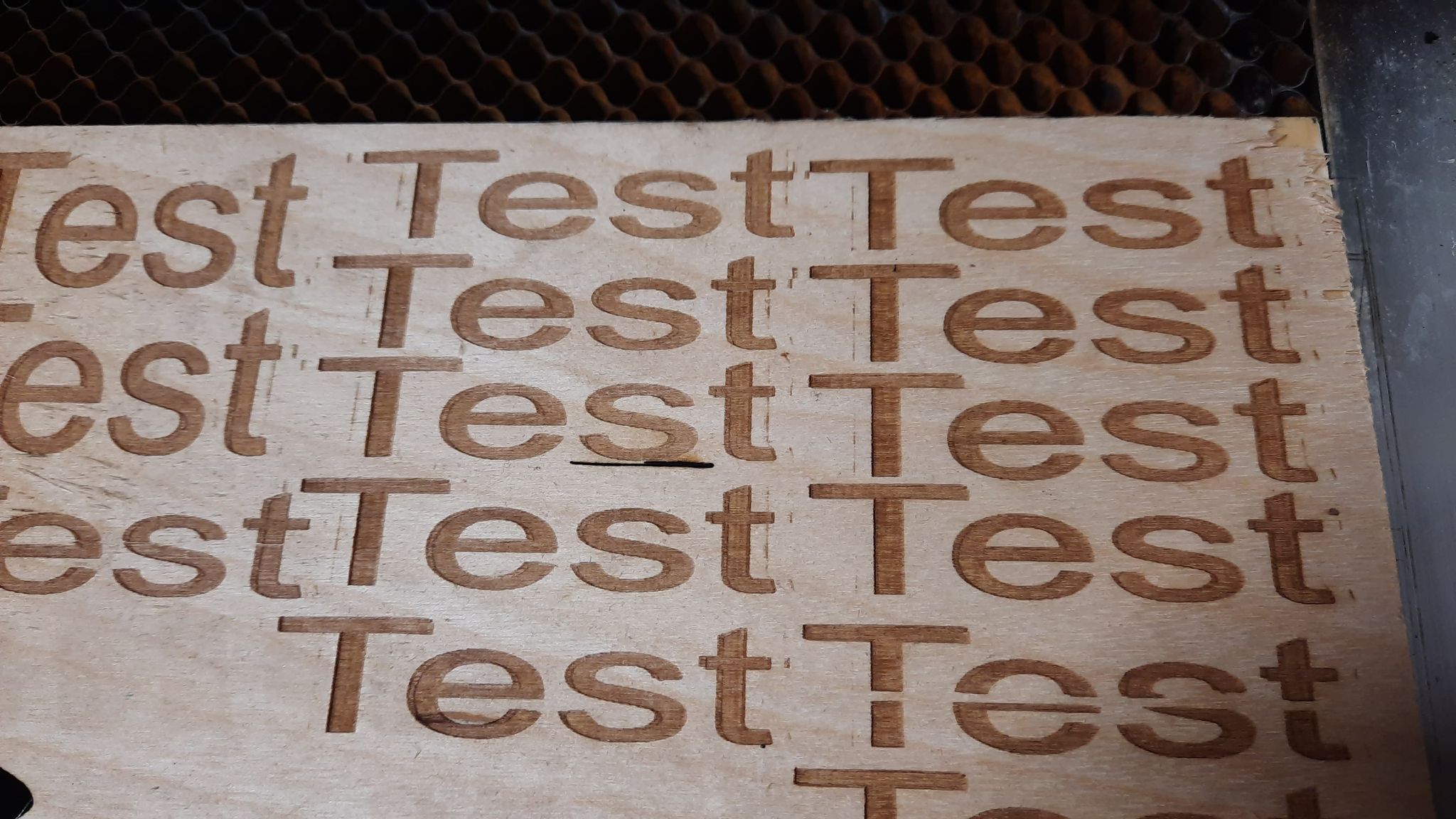
Just now I wrapped all the wiring back up (separate pairs, as it should be) and it has never etched this good! Super clean edges!Note: for w/e reason Acrylic Glass (backside facing up) will show the smallest amount of lasering that will not show up even on paper etc, thus why I use it for testing)
Eric
So looks like I found the culprit.
I just finished my new 48x48 CNC Router build and learned a lot about EMI using a Spindle and VFD on this build, that got me thinking about my laser wiring…
I moved some wires and the MiniG around (power off) and on the next test it was worse so I knew I was on to something.
When I did the MiniG upgrade I removed all the spiral wire wrap due to all the needed rewiring but never installed it back.
Just now I wrapped all the wiring back up (separate pairs, as it should be) and it has never etched this good! Super clean edges!
Note: for w/e reason Acrylic Glass (backside facing up) will show the smallest amount of lasering that will not show up even on paper etc, thus why I use it for testing)
Eric
Quote from Paul on October 20, 2019, 7:33 amGood find Eric and shows how complex these tiny issues can be. The resistance on the big power connector can also play a role. Reseating it firmly and straight often fixes these faint lines issues as well.
Well done! Cheers, Paul
Good find Eric and shows how complex these tiny issues can be. The resistance on the big power connector can also play a role. Reseating it firmly and straight often fixes these faint lines issues as well.
Well done! Cheers, Paul
Quote from Dbtoutfit on November 19, 2020, 1:08 pmI have had this come and go since I got the MG.
I have replaced wires, soldered the molex plug pins. I get it to stop for a short while and its back at it again and something else. This time I have worked for 4 days trying to find the exact issue.I can move wires around and the issues fades, or stops and then will come and go during the engraving process (sold vectors only, no raster or grey scale).
I have even purchased another power supply to make sure that wasn't the issue.
I can't find a "short" but it's like a resistance or interference or need to be better PMW grounding to reach ZERO laser output. Off is never truly "off".
My machine measures 2Ohms from ground pin to PSU case.
I am at a lost as to what to try next and deflated at this point. I have orders to complete and ruining product in the process.
I could really use some serious help.
Thanks,
Eric
I have had this come and go since I got the MG.
I have replaced wires, soldered the molex plug pins. I get it to stop for a short while and its back at it again and something else. This time I have worked for 4 days trying to find the exact issue.
I can move wires around and the issues fades, or stops and then will come and go during the engraving process (sold vectors only, no raster or grey scale).
I have even purchased another power supply to make sure that wasn't the issue.
I can't find a "short" but it's like a resistance or interference or need to be better PMW grounding to reach ZERO laser output. Off is never truly "off".
My machine measures 2Ohms from ground pin to PSU case.
I am at a lost as to what to try next and deflated at this point. I have orders to complete and ruining product in the process.
I could really use some serious help.
Thanks,
Eric
Quote from Dbtoutfit on November 20, 2020, 1:35 pmOk so I think I finally got it for good.
In the wiring document it states the 5v and GND of the PWM 3pin plug doesn't need to be wired - only the PWM pin needs to be wired of your PSU.
After disconnecting every non-essential wire trying to discover the interference and what seem to be a lack of grounded it looks as though I have found the problem.
On my Digital PSU I wired the GND to the MiniG GND on the set of headers to the pin labeled GND next to first header that the PWM is on. The issue immediately went away and hasn't returned.
Hope this helps someone that is getting a line or ghosting of scans/etching where the PMW is floating which allows the laser to have a low power output - never really turning it off.
Thanks
Ok so I think I finally got it for good.
In the wiring document it states the 5v and GND of the PWM 3pin plug doesn't need to be wired - only the PWM pin needs to be wired of your PSU.
After disconnecting every non-essential wire trying to discover the interference and what seem to be a lack of grounded it looks as though I have found the problem.
On my Digital PSU I wired the GND to the MiniG GND on the set of headers to the pin labeled GND next to first header that the PWM is on. The issue immediately went away and hasn't returned.
Hope this helps someone that is getting a line or ghosting of scans/etching where the PMW is floating which allows the laser to have a low power output - never really turning it off.
Thanks
Quote from Paul on November 20, 2020, 2:35 pmThanks dbtoutfit, that's a great outcome. In the stock psu, the various gnd signals are the same. It could be that the connection within the psu is a bad solder joint so the common gnd is not working. Adding a second gnd wire solves that issue. I will put that into the trouble shooting list of possible issues. Well done!
Thanks dbtoutfit, that's a great outcome. In the stock psu, the various gnd signals are the same. It could be that the connection within the psu is a bad solder joint so the common gnd is not working. Adding a second gnd wire solves that issue. I will put that into the trouble shooting list of possible issues. Well done!
Quote from Dbtoutfit on November 21, 2020, 12:28 pmWished it didn't take me so long to find.
See above where I mentioned purchasing a second PSU to rule out a PSU problem. No dry solder socket on header pin of the PSU.
Maybe with these digital PSUs the GND is not across rails? If not why did they use the 3pin GND/PMW/5v header?
Whats the 5v pin for anyways?
Eric
Wished it didn't take me so long to find.
See above where I mentioned purchasing a second PSU to rule out a PSU problem. No dry solder socket on header pin of the PSU.
Maybe with these digital PSUs the GND is not across rails? If not why did they use the 3pin GND/PMW/5v header?
Whats the 5v pin for anyways?
Eric
Quote from Paul on November 22, 2020, 10:30 amHi, the gnd points are connected to each other via a copper track on the PSU board. Best to measure with a multimeter in Ohm setting.(of course PSU turned off)
The 5V on the three pin connector (or screw terminal rails) are used for the K40 versions with an analogue power setting (potmeter). The 5V is divided via the potmeter (whisker or middle leg is connected to the IN point) to a reference voltage.
In those setups, the LO signal is used to turn on and off the laser head. Unfortunately this does not work in LightBurn since the developer of that software uses just the strength parm S (which is the IN connection) to turn off the laser and leaves the LO continuous on for speed conveniences (lasering is much faster in such a setup)
Cheers!
Hi, the gnd points are connected to each other via a copper track on the PSU board. Best to measure with a multimeter in Ohm setting.(of course PSU turned off)
The 5V on the three pin connector (or screw terminal rails) are used for the K40 versions with an analogue power setting (potmeter). The 5V is divided via the potmeter (whisker or middle leg is connected to the IN point) to a reference voltage.
In those setups, the LO signal is used to turn on and off the laser head. Unfortunately this does not work in LightBurn since the developer of that software uses just the strength parm S (which is the IN connection) to turn off the laser and leaves the LO continuous on for speed conveniences (lasering is much faster in such a setup)
Cheers!
Quote from Dbtoutfit on November 23, 2020, 4:15 amBeen so long since I had my POT hooked up I didn't think about that.
However my NewlyDraw board had to have all 3 wires via a DAC hooked up to the PSU PWM header.I get 20 Ohms from the PWM GND Pin to the PSU case and same from Power GND Pin to PSU case. I do not get a reading across PWM and Power GND Pins.
Regardless, I should be getting GND from the Power GND pin so it would seem to me the disconnect is on the MG side.
Thanks
Been so long since I had my POT hooked up I didn't think about that.
However my NewlyDraw board had to have all 3 wires via a DAC hooked up to the PSU PWM header.
I get 20 Ohms from the PWM GND Pin to the PSU case and same from Power GND Pin to PSU case. I do not get a reading across PWM and Power GND Pins.
Regardless, I should be getting GND from the Power GND pin so it would seem to me the disconnect is on the MG side.
Thanks