
Non zero PWM/Wiring laser trigger with Super Gerbil
Quote from Deleted user on August 5, 2019, 10:35 amGoing into day 3 of troubleshooting my CO2 laser setup and I'm clueless as to what is causing my issues. Hopefully someone here has some ideas. Any help is greatly appreciated!
Noted Problems:
PWM--
So poking around with the meter I've discovered that the positive PWM varies between 0.4 and 5.0V RMS and the negative PWM varies between 0.2 and 5.0V RMS. 0.2V seems to be just enough for the laser to randomly fire at the lowest possible power. Normally this wouldn't be an issue but I'm also having triggering problems.
Triggering--
I'm not entirely certain that this is the correct way to trigger with the SG but its how the 455nm diode laser is triggered on my other machine with an arduino so it's what I've done. I'm using the spindle direction pin for the spindle driver. This pin goes high on an M4 or an M5 and low on an M3. I've also tried the spindle enable in the same row of pins which only goes high on an M5. When connected to the trigger low on the PSU both DIR and EN cause the PSU to stay triggered all the time, M5 causes a full power fire as it sends the negative PWM to 5V. When connected to the trigger high, the enable pin triggers only on M5 which is obviously not useful, while the direction pin triggers on M4 and M5. My ideal setup would be using the direction pin with positive PWM if we could work that out. I'm suspecting this is caused by my wiring or possibly an issue with the PSU as it is also new.My Wiring Setup:
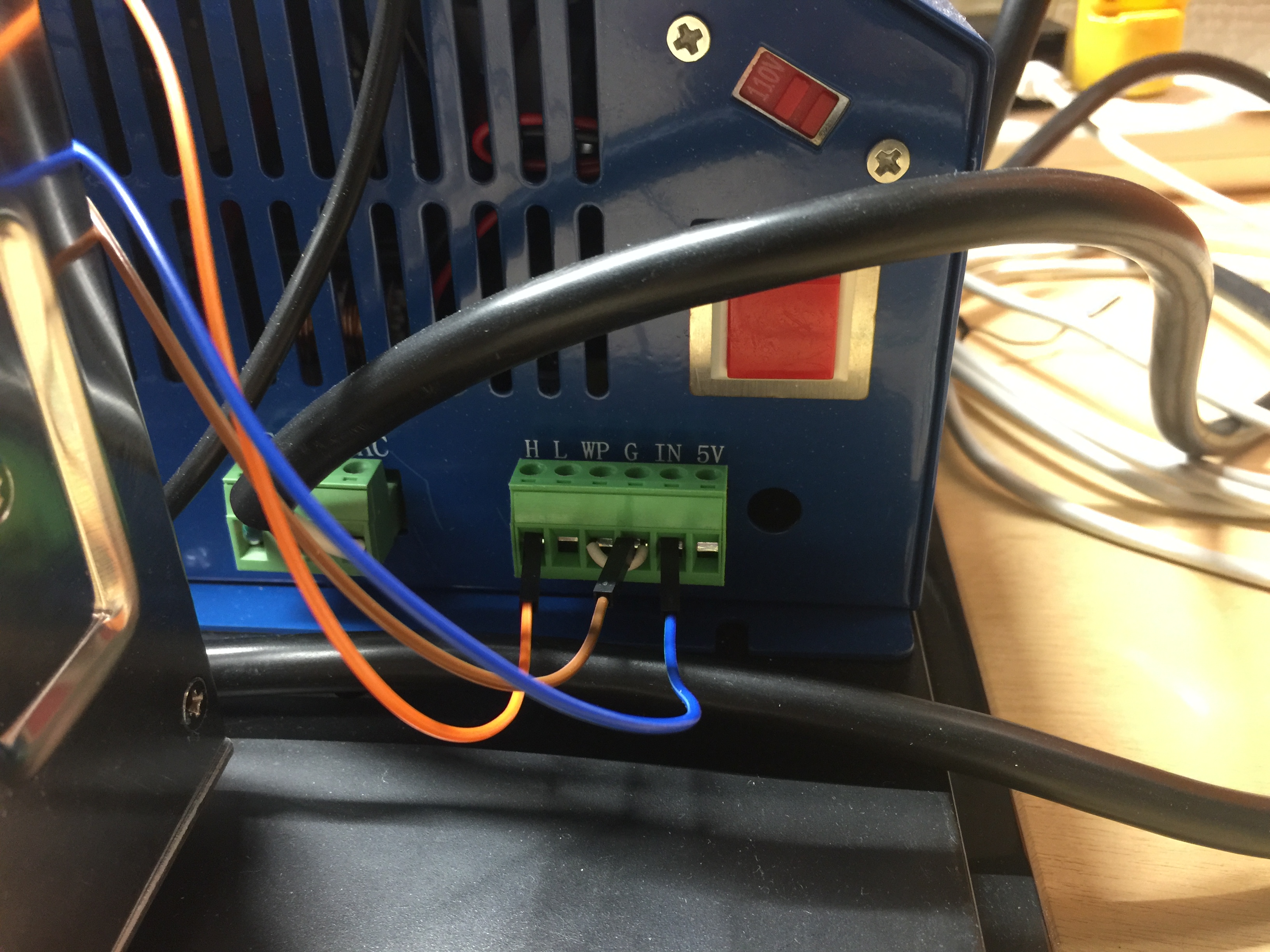
The laser PSU has pins for trigger high, trigger low, water protect, ground, PWM IN, and 5V out. I run my trigger wire from either spindle direction or enable pins on the spindle driver port to either trigger high or low on the PSU. The ground pin on the spindle driver port I have running to the ground on the PSU (this seems wrong to me due to the difference in potentials but I'm still learning hobby electronics and this is the only way I found to make the trigger work). The water protect is jumpered to the ground as I have no flow sensor at the moment. The negative PWM from the SG is connected to the IN on the PSU and the ground for the negative PWM is connected to the ground on the PSU. Finally, the 5V out on the PSU is connected to the Vin on the SG PWM section.
For reference all other tested functions of the SG work perfectly it is only the isolated PWM that seems to behave usually.
Going into day 3 of troubleshooting my CO2 laser setup and I'm clueless as to what is causing my issues. Hopefully someone here has some ideas. Any help is greatly appreciated!
Noted Problems:
PWM--
So poking around with the meter I've discovered that the positive PWM varies between 0.4 and 5.0V RMS and the negative PWM varies between 0.2 and 5.0V RMS. 0.2V seems to be just enough for the laser to randomly fire at the lowest possible power. Normally this wouldn't be an issue but I'm also having triggering problems.
Triggering--
I'm not entirely certain that this is the correct way to trigger with the SG but its how the 455nm diode laser is triggered on my other machine with an arduino so it's what I've done. I'm using the spindle direction pin for the spindle driver. This pin goes high on an M4 or an M5 and low on an M3. I've also tried the spindle enable in the same row of pins which only goes high on an M5. When connected to the trigger low on the PSU both DIR and EN cause the PSU to stay triggered all the time, M5 causes a full power fire as it sends the negative PWM to 5V. When connected to the trigger high, the enable pin triggers only on M5 which is obviously not useful, while the direction pin triggers on M4 and M5. My ideal setup would be using the direction pin with positive PWM if we could work that out. I'm suspecting this is caused by my wiring or possibly an issue with the PSU as it is also new.
My Wiring Setup:
The laser PSU has pins for trigger high, trigger low, water protect, ground, PWM IN, and 5V out. I run my trigger wire from either spindle direction or enable pins on the spindle driver port to either trigger high or low on the PSU. The ground pin on the spindle driver port I have running to the ground on the PSU (this seems wrong to me due to the difference in potentials but I'm still learning hobby electronics and this is the only way I found to make the trigger work). The water protect is jumpered to the ground as I have no flow sensor at the moment. The negative PWM from the SG is connected to the IN on the PSU and the ground for the negative PWM is connected to the ground on the PSU. Finally, the 5V out on the PSU is connected to the Vin on the SG PWM section.
For reference all other tested functions of the SG work perfectly it is only the isolated PWM that seems to behave usually.
Quote from Paul on August 5, 2019, 10:57 amHi, it seems that the LO connection is 'on' (zero volt) at all times otherwise the random triggering of the laser should not happen. M4 should give zero (negative logic) and M5 should give 5V (or above at least 2.5v). If you use the set up as laser, make sure you put the SG in laser mode via $32=1. Using it in CNC mode is fine for testing but CNC mode works with M3 while laser mode uses M4.
Some resistance in the connector pins could possible cause these types of issues as well.
Another option is to use the PWM output pin at the Spindle driver module socket. Just use the GND and PWM pins. You can insert a header row into the socket for easy connection.
Hope this helps, please let us know.
Hi, it seems that the LO connection is 'on' (zero volt) at all times otherwise the random triggering of the laser should not happen. M4 should give zero (negative logic) and M5 should give 5V (or above at least 2.5v). If you use the set up as laser, make sure you put the SG in laser mode via $32=1. Using it in CNC mode is fine for testing but CNC mode works with M3 while laser mode uses M4.
Some resistance in the connector pins could possible cause these types of issues as well.
Another option is to use the PWM output pin at the Spindle driver module socket. Just use the GND and PWM pins. You can insert a header row into the socket for easy connection.
Hope this helps, please let us know.
Quote from Deleted user on August 5, 2019, 11:48 amJust tested using the spindle driver PWM and that should do the job. It maxes out at around 3V(same as the direction and enable pins) but this is more than enough to get the PSU to the max tube current. Huge thanks, I have no idea why I didn't consider trying that before. I'm now using the spindle direction for the trigger high which allows for M3 to be off and M4 to be PWM. M5 will still need to be pulled from the programs as it will overload the laser. In the future I'll likely try to invert the spindle PWM in the SG firmware to fix this, but for now this should be a functional machine.
$28 for PWM frequency affects the spindle driver PWM as well right? Or is that strictly on the opto-isolated output?
Just tested using the spindle driver PWM and that should do the job. It maxes out at around 3V(same as the direction and enable pins) but this is more than enough to get the PSU to the max tube current. Huge thanks, I have no idea why I didn't consider trying that before. I'm now using the spindle direction for the trigger high which allows for M3 to be off and M4 to be PWM. M5 will still need to be pulled from the programs as it will overload the laser. In the future I'll likely try to invert the spindle PWM in the SG firmware to fix this, but for now this should be a functional machine.
$28 for PWM frequency affects the spindle driver PWM as well right? Or is that strictly on the opto-isolated output?
Quote from Paul on August 6, 2019, 11:09 amHi, I just recalled the min pwm setting $31. You probably need to set that to zero as well.
The setting $28 for PWM frequency affects the spindle driver PWM as well.
cheers, Paul
Hi, I just recalled the min pwm setting $31. You probably need to set that to zero as well.
The setting $28 for PWM frequency affects the spindle driver PWM as well.
cheers, Paul
Quote from Deleted user on August 26, 2019, 8:50 amFinally got my mirror alignment to a good enough level to run some files and cutting is working out great but for some reason I can't get $32=1 (Laser Mode) to activate so I can engrave. I've tried 2 PCs with 2 different versions of UGS and also a version of OpenBuilds Control but this doesn't seem to change anything. I've also tried exporting the settings file from UGS, editing it in Notepad++, and importing it back in but every time I send a $$ it returns $32=0. Any ideas as to what this might be? I suppose the next option is to break out the ST-Link and flash the board? I'm almost certain I had it in laser mode at some point but perhaps I'm mistaken.
Finally got my mirror alignment to a good enough level to run some files and cutting is working out great but for some reason I can't get $32=1 (Laser Mode) to activate so I can engrave. I've tried 2 PCs with 2 different versions of UGS and also a version of OpenBuilds Control but this doesn't seem to change anything. I've also tried exporting the settings file from UGS, editing it in Notepad++, and importing it back in but every time I send a $$ it returns $32=0. Any ideas as to what this might be? I suppose the next option is to break out the ST-Link and flash the board? I'm almost certain I had it in laser mode at some point but perhaps I'm mistaken.
Quote from Paul on August 26, 2019, 9:34 amUse another G-code sender e.g. CNCjs to send G-codes directly to the controller. Issue a $32=1 and it should register. Alternatively you can download a trial version of LightBurn or use laser web.
Cheers, Paul
Use another G-code sender e.g. CNCjs to send G-codes directly to the controller. Issue a $32=1 and it should register. Alternatively you can download a trial version of LightBurn or use laser web.
Cheers, Paul
Quote from Deleted user on August 26, 2019, 10:09 amJust tried both CNCjs and LaserWeb. Still no change unfortunately.
Just tried both CNCjs and LaserWeb. Still no change unfortunately.
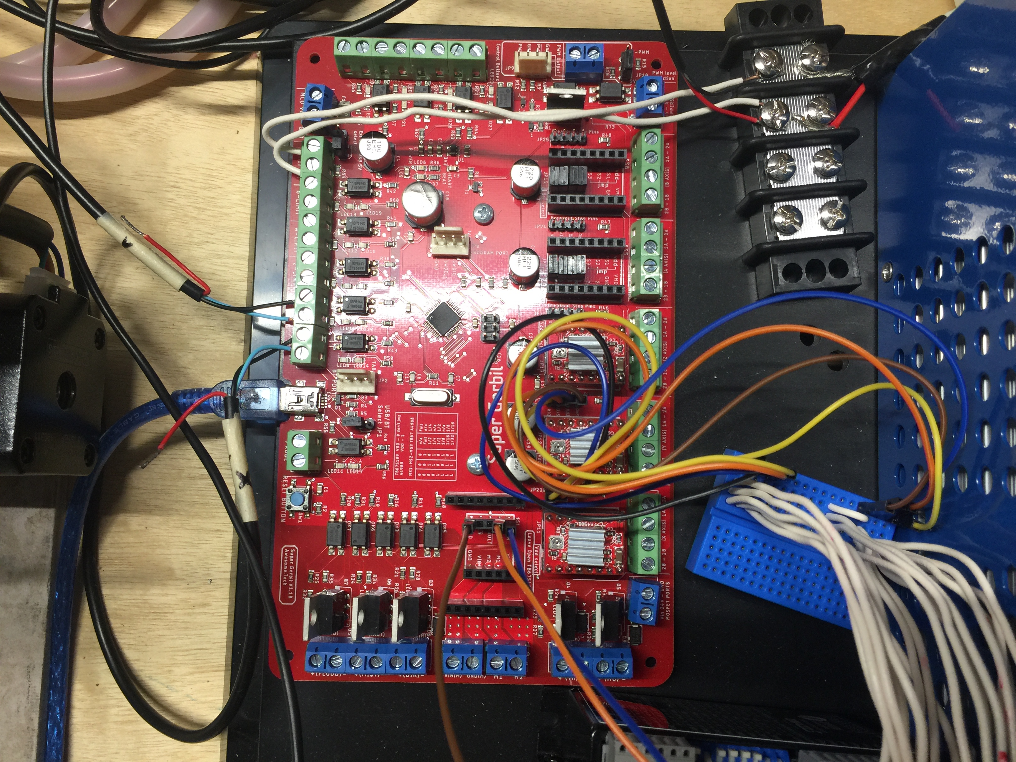
Quote from Deleted user on August 26, 2019, 1:55 pmI have a few quick photos that should show everything that might affect this. I can draw up a wiring diagram tomorrow if that is necessary. A few notes:
- The terminal block in the top right of the SG photo is 5V from a usb tablet charger.
- The blue breadboard on the right side of the same photo just links the SG stepper breakouts to the x and dual y external drivers. Those get 24V from a separate supply.
- Wire colors are consistent from the spindle driver to the laser supply.
I have a few quick photos that should show everything that might affect this. I can draw up a wiring diagram tomorrow if that is necessary. A few notes:
- The terminal block in the top right of the SG photo is 5V from a usb tablet charger.
- The blue breadboard on the right side of the same photo just links the SG stepper breakouts to the x and dual y external drivers. Those get 24V from a separate supply.
- Wire colors are consistent from the spindle driver to the laser supply.
Quote from Paul on August 27, 2019, 10:05 amI suppose the next option is to break out the ST-Link and flash the board?
You might want to try to re-flash the controller? Note- you need the st link software from st.com (free) and hold the reset button, release it and click on the connect button in the st-link software application. This releases two ports from their current function for use as software programmer ports. This is a bit tricky, timing is everything so give it a few tries.
I suppose the next option is to break out the ST-Link and flash the board?
You might want to try to re-flash the controller? Note- you need the st link software from st.com (free) and hold the reset button, release it and click on the connect button in the st-link software application. This releases two ports from their current function for use as software programmer ports. This is a bit tricky, timing is everything so give it a few tries.
Quote from Deleted user on August 27, 2019, 12:45 pmWell I was pretty confident that would have solved it but I did clean flashes with both hexs on the github page and no luck. I still get the ok message after I send a $32=1 but then a $$ shows no change on $32. All other grbl settings save correctly.
As a side note I've found that, with my setup at least, the ST-Link connects quite reliably if you hold the SG reset, click connect, then wait a second before releasing the button.
I'm pretty stumped at this point but I appreciate all the help from Paul and anyone else who might have any ideas.
Well I was pretty confident that would have solved it but I did clean flashes with both hexs on the github page and no luck. I still get the ok message after I send a $32=1 but then a $$ shows no change on $32. All other grbl settings save correctly.
As a side note I've found that, with my setup at least, the ST-Link connects quite reliably if you hold the SG reset, click connect, then wait a second before releasing the button.
I'm pretty stumped at this point but I appreciate all the help from Paul and anyone else who might have any ideas.