
No ribbon cable and newer mini gerbil with a few other questions.
Quote from Kelsh on January 31, 2020, 4:19 pmI have a K40 that does not have the ribbon cable. I got one of the newer mini gerbils that has all the connectors in a row, with a 5 pin connector behind the ribbon connector.
I've tried reading the instructions in the post about having no ribbon cable but it's for older style mini gerbil boards and I'm having trouble translating it to the newer layout. I think I have the wiring diagram translated correctly but I want to be certain.
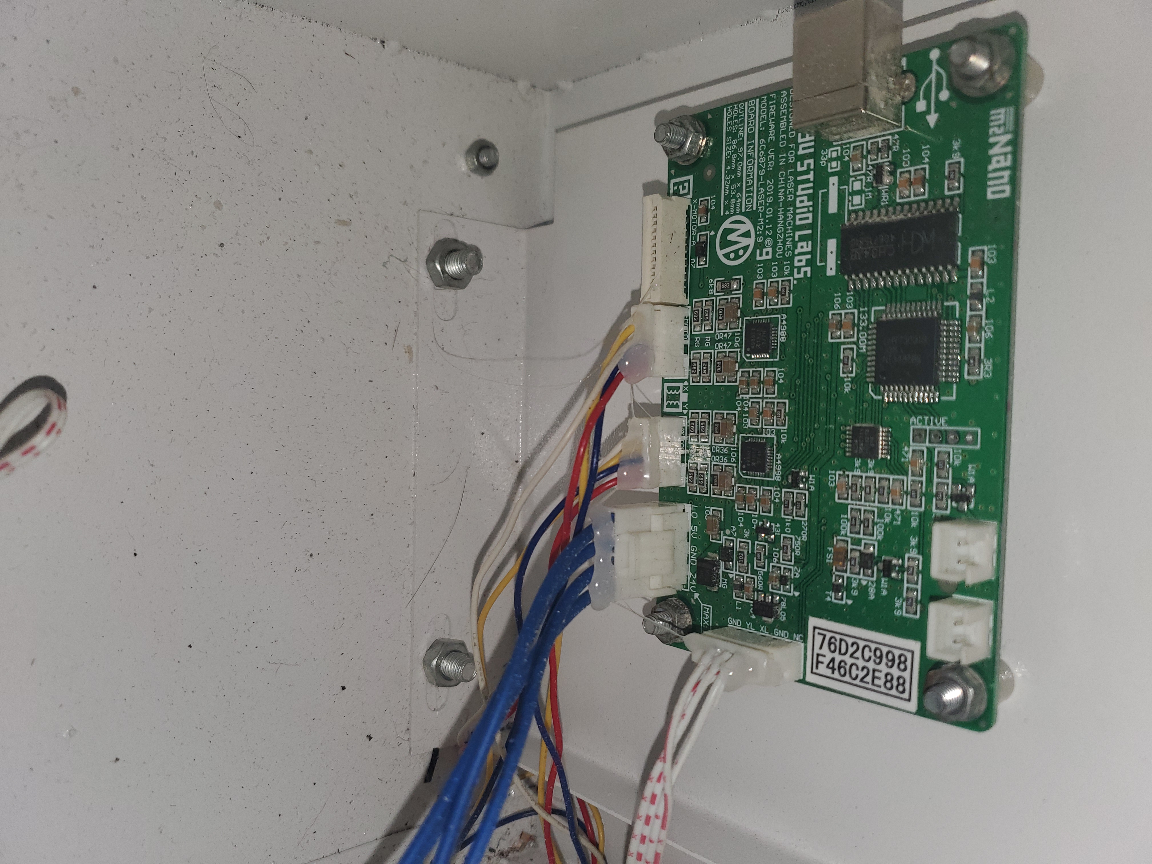
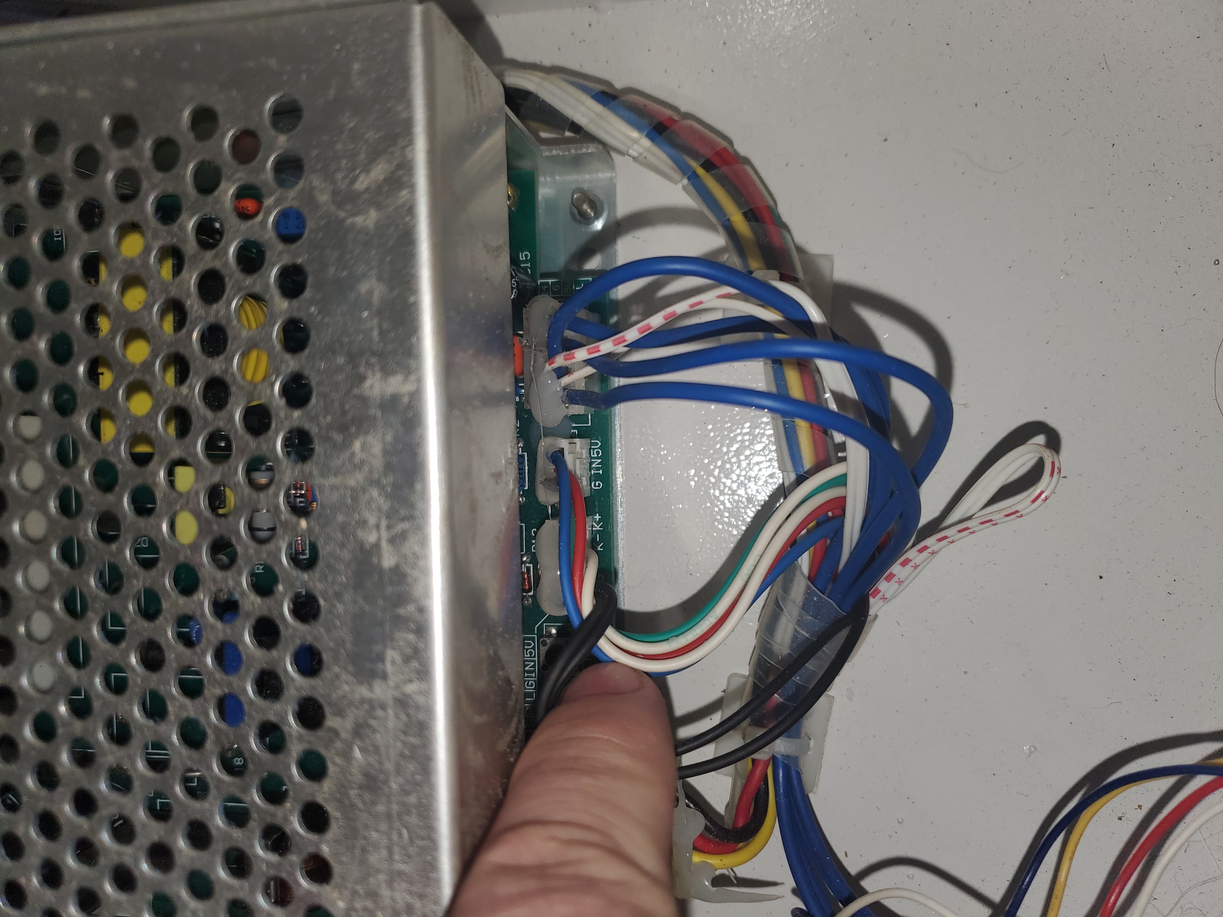
I'm attaching images of my power supply and my original controller. I have some questions:
- It would appear that my yellow and white wires on the Y axis motor connector are swapped, is that normal?
- I can push the existing XY limits cable onto the connector behind the ribbon cable connector with the Gnd, X, and Y wires lined up although it pushes the cable out at a bit of an angle, does that matter? (I have mechanical limit switches so it sounds like I don't need to worry about the 5V connector.)
- The existing connectors for the X and Y motors are too wide to both go on the plugs on the mini gerbil. I can push one on but the other will not fit on it while the one is connected. Does that mean I need to get these? https://www.jaycar.com.au/4-pin-0-1-header-with-crimp-pins-2-54-pitch/p/HM3404 (I'll have to find a US supplier.)
- Assuming I need new connectors, should I keep the wires in the same order in the new connectors as they are in the old connectors or should I swap the white and yellow for Y (see 1)?
- Is the red connector on the IN line to the power supply the correct one to replace with the PWM line going to the mini gerbil?
Sorry about all the questions. I think I interpreted all the information I found in other posts correctly but I want to be sure before I order connectors and fire it up.
Thank you!
I have a K40 that does not have the ribbon cable. I got one of the newer mini gerbils that has all the connectors in a row, with a 5 pin connector behind the ribbon connector.
I've tried reading the instructions in the post about having no ribbon cable but it's for older style mini gerbil boards and I'm having trouble translating it to the newer layout. I think I have the wiring diagram translated correctly but I want to be certain.
I'm attaching images of my power supply and my original controller. I have some questions:
- It would appear that my yellow and white wires on the Y axis motor connector are swapped, is that normal?
- I can push the existing XY limits cable onto the connector behind the ribbon cable connector with the Gnd, X, and Y wires lined up although it pushes the cable out at a bit of an angle, does that matter? (I have mechanical limit switches so it sounds like I don't need to worry about the 5V connector.)
- The existing connectors for the X and Y motors are too wide to both go on the plugs on the mini gerbil. I can push one on but the other will not fit on it while the one is connected. Does that mean I need to get these? https://www.jaycar.com.au/4-pin-0-1-header-with-crimp-pins-2-54-pitch/p/HM3404 (I'll have to find a US supplier.)
- Assuming I need new connectors, should I keep the wires in the same order in the new connectors as they are in the old connectors or should I swap the white and yellow for Y (see 1)?
- Is the red connector on the IN line to the power supply the correct one to replace with the PWM line going to the mini gerbil?
Sorry about all the questions. I think I interpreted all the information I found in other posts correctly but I want to be sure before I order connectors and fire it up.
Thank you!
Uploaded files: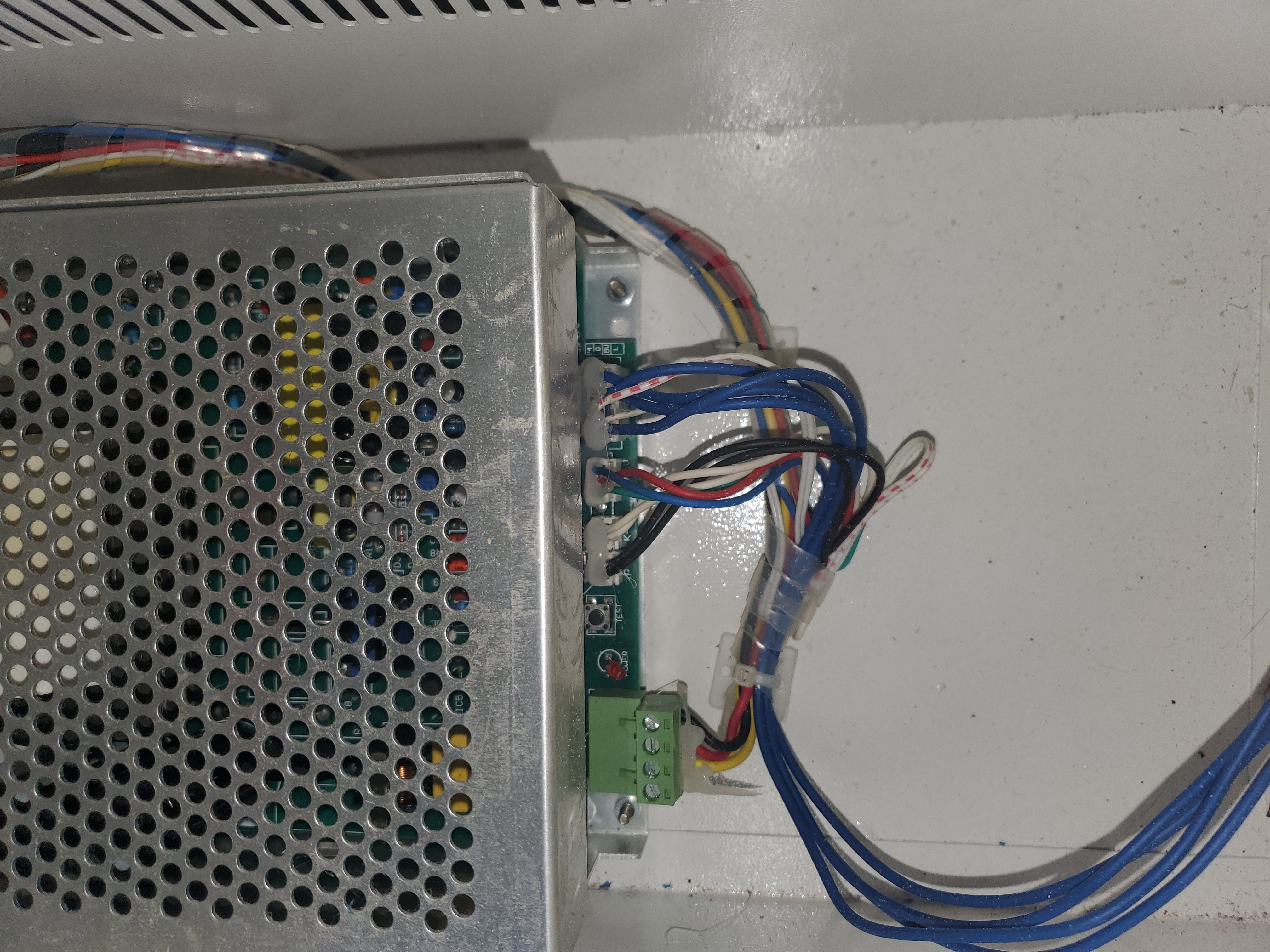
Quote from Kelsh on February 1, 2020, 4:59 pmI tried it out. I found a local supply company that had the correct 4 pin nylon connectors.
I put the wires in the same order as they were in the older plugs and plugged the new plugs in.
Through Lightburn, I had to change the X Direction pin invert ($3) to False and the Y Direction pin invert ($3) to True because it started out homing to the bottom right, and pressing the move arrow buttons in Lightburn made the laser head travel in the opposite direction.
My $10 came set to 31, I could only press the arrow buttons in Lightburn 1 or 2 times before it would stop responding and the busy line stayed full. Changing $10 to 1 seems to have corrected that issue.
The plugs on the power supply are different enough that I could not use the wires included for the PWM signal. I had to use a wire from an old PC that had a similar connector (the metal part that is inside the slot in the plug) and press it into the plug to the pin on the power supply.
I have not yet fired the laser, that's my next steps.
I tried it out. I found a local supply company that had the correct 4 pin nylon connectors.
I put the wires in the same order as they were in the older plugs and plugged the new plugs in.
Through Lightburn, I had to change the X Direction pin invert ($3) to False and the Y Direction pin invert ($3) to True because it started out homing to the bottom right, and pressing the move arrow buttons in Lightburn made the laser head travel in the opposite direction.
My $10 came set to 31, I could only press the arrow buttons in Lightburn 1 or 2 times before it would stop responding and the busy line stayed full. Changing $10 to 1 seems to have corrected that issue.
The plugs on the power supply are different enough that I could not use the wires included for the PWM signal. I had to use a wire from an old PC that had a similar connector (the metal part that is inside the slot in the plug) and press it into the plug to the pin on the power supply.
I have not yet fired the laser, that's my next steps.
Quote from Kelsh on February 1, 2020, 5:33 pmThe macro to test fire the laser turned it on but did not turn it off, I'm unsure why.
I made a 40mmx40mm box in lightburn and test cut it with varying power settings. It worked.
For my machine, the power percentages worked out to the following displayed on the mA meter:
15% = ~6mA
20% = ~7.5mA
25% = ~9mA
The macro to test fire the laser turned it on but did not turn it off, I'm unsure why.
I made a 40mmx40mm box in lightburn and test cut it with varying power settings. It worked.
For my machine, the power percentages worked out to the following displayed on the mA meter:
15% = ~6mA
20% = ~7.5mA
25% = ~9mA
Quote from dancolwp1974 on February 9, 2020, 4:48 pmHi Kelsh,
To answer your original questions.
1. There are multiple factories that make K40's and there's no guarantees that they use the same color wiring. So when you see photos of other units with wire colors in different positions, don't worry about it as it's only the wire positions that matter.
2. It sounds ok - connectors don't always mate perfectly. As long as it looks like the conductors are connecting reliably, it should be ok.
3. Apologies that the Mini Gerbil sockets appear too tightly spaced for your plugs - we haven't had that issue before, I'm guessing it must be less than a mm of overlap? While you could find alternative plugs at an electronic parts retailer, I'd be tempted to pare back the plastic housing of your two plugs where they would interfere with eachother. With the power off, use a small hand file, being careful not to file insulation or the metal contacts.
4. Yes, order is what matters, not insulation color.
5. Yes, remove the wire at the IN terminal (red in your case) and insert the PWM line from the Mini Gerbil.
All the actions you've listed in your second post sound correct.
Re the Test Fire macro not turning off the laser beam, please note that a LightBurn fix came out that should resolve this:
https://forum.lightburnsoftware.com/t/macro-not-running/6503I gather since you got your test box burnt, everything is running ok now?
Regards,
DanPS Am working on improving the installation instructions, thanks for your patience with the current ones.
Hi Kelsh,
To answer your original questions.
1. There are multiple factories that make K40's and there's no guarantees that they use the same color wiring. So when you see photos of other units with wire colors in different positions, don't worry about it as it's only the wire positions that matter.
2. It sounds ok - connectors don't always mate perfectly. As long as it looks like the conductors are connecting reliably, it should be ok.
3. Apologies that the Mini Gerbil sockets appear too tightly spaced for your plugs - we haven't had that issue before, I'm guessing it must be less than a mm of overlap? While you could find alternative plugs at an electronic parts retailer, I'd be tempted to pare back the plastic housing of your two plugs where they would interfere with eachother. With the power off, use a small hand file, being careful not to file insulation or the metal contacts.
4. Yes, order is what matters, not insulation color.
5. Yes, remove the wire at the IN terminal (red in your case) and insert the PWM line from the Mini Gerbil.
All the actions you've listed in your second post sound correct.
Re the Test Fire macro not turning off the laser beam, please note that a LightBurn fix came out that should resolve this:
https://forum.lightburnsoftware.com/t/macro-not-running/6503
I gather since you got your test box burnt, everything is running ok now?
Regards,
Dan
PS Am working on improving the installation instructions, thanks for your patience with the current ones.
Quote from Kelsh on February 12, 2020, 4:42 pmI apologize for the delay getting back to you, I've been attempting to troubleshoot the issues I've been having since I got everything hooked up with the mini-gerbil and Lightburn within the Lightburn forums.
At first I replaced the connectors for the motor drivers with nylon terminal housing connectors but I realized I couldn't go back to the old board with those plugs. I got JST connectors to replace the plugs, taking them back to what they were, and found that by cutting the tabs off the top of the plugs I could fit them on the connectors on the mini-gerbil and the old nano as well. (The clips that give plug orientation on the mini-gerbil snapped but the plugs still plug in solidly.)
Now I'm fighting an issue with ghosting/offset when I attempt to raster engrave the same file in lightburn with the mini-gerbil that is clean with the nano and k40 whisperer. If I switch back to the nano, the image/text are clear (especially the small text) but if I go to lightburn and set what I believe are the same settings, I get blurred images and text.
The file I'm using was originally created in Lightburn by using the trace image tool, exported as an svg, I then tweaked the document size in inkscape, and then ran it from k40 whisperer. It came out with clean lines and text that way.
I tried running the original lightburn file and the svg from lightburn and at this point I'm running out of configurations to attempt. I've tried numerous speeds from 100mm/s to 300mm/s and power settings from 10% to 20%. I've tried setting overscan on and off. I've tried finding the text font and typing in the lettering to raster that instead. I've tried pulling the image as a bmp and rastering that. It all winds up with blurred text and sloppy images in lightburn and the mini-gerbil.
The images you see in the attached in the top left were when I started attempting to set a scan offset per the suggestion of the Lightburn moderator. The top right hillsboro nazarene image is where I stopped attempting to adjust the offset because it looked like the horizontal is ok but there is a vertical offset between lines now.
This only seems to effect raster engraving on lightburn and the mini-gerbil. If I cut lines with the mini-gerbil and lightburn or if I switch back to the nano and k40 whisperer to engrave/cut, I have no issues.
The engraving on the lighter wood is when I switched back to the nano and k40 whisperer. (I have a male plug coming off the In lead to the power supply now and female plugs on the leads for the mA meter/potentiometer and the wire to PWM on the mini-gerbil so I can swap them more easily.)
I'm really at a loss as to what to do next.
I apologize for the delay getting back to you, I've been attempting to troubleshoot the issues I've been having since I got everything hooked up with the mini-gerbil and Lightburn within the Lightburn forums.
At first I replaced the connectors for the motor drivers with nylon terminal housing connectors but I realized I couldn't go back to the old board with those plugs. I got JST connectors to replace the plugs, taking them back to what they were, and found that by cutting the tabs off the top of the plugs I could fit them on the connectors on the mini-gerbil and the old nano as well. (The clips that give plug orientation on the mini-gerbil snapped but the plugs still plug in solidly.)
Now I'm fighting an issue with ghosting/offset when I attempt to raster engrave the same file in lightburn with the mini-gerbil that is clean with the nano and k40 whisperer. If I switch back to the nano, the image/text are clear (especially the small text) but if I go to lightburn and set what I believe are the same settings, I get blurred images and text.
The file I'm using was originally created in Lightburn by using the trace image tool, exported as an svg, I then tweaked the document size in inkscape, and then ran it from k40 whisperer. It came out with clean lines and text that way.
I tried running the original lightburn file and the svg from lightburn and at this point I'm running out of configurations to attempt. I've tried numerous speeds from 100mm/s to 300mm/s and power settings from 10% to 20%. I've tried setting overscan on and off. I've tried finding the text font and typing in the lettering to raster that instead. I've tried pulling the image as a bmp and rastering that. It all winds up with blurred text and sloppy images in lightburn and the mini-gerbil.
The images you see in the attached in the top left were when I started attempting to set a scan offset per the suggestion of the Lightburn moderator. The top right hillsboro nazarene image is where I stopped attempting to adjust the offset because it looked like the horizontal is ok but there is a vertical offset between lines now.
This only seems to effect raster engraving on lightburn and the mini-gerbil. If I cut lines with the mini-gerbil and lightburn or if I switch back to the nano and k40 whisperer to engrave/cut, I have no issues.
The engraving on the lighter wood is when I switched back to the nano and k40 whisperer. (I have a male plug coming off the In lead to the power supply now and female plugs on the leads for the mA meter/potentiometer and the wire to PWM on the mini-gerbil so I can swap them more easily.)
I'm really at a loss as to what to do next.
Uploaded files: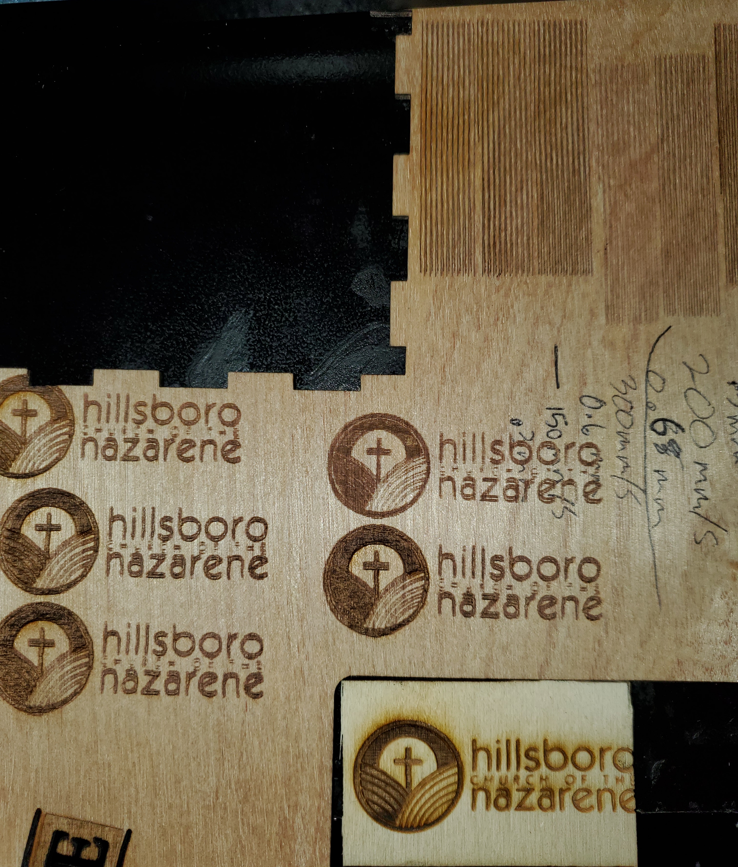
Quote from dancolwp1974 on February 12, 2020, 10:42 pmHi Kelsh,
My first impression is that this seems like a challenge of finding the right power/speed setting, but appreciate you've already tried a number of combinations.
The Mini Gerbil engraves better than Nano, often without any adjustment. Because the engraving is sensitive to so many factors (the laser beam, optics, image, material and control electronics), sometimes the image needs tweaking to achieve the better result. If you or your contacts have any knowledge of photography, that's handy because the image related skills transfer to laser engraving. For example, using a graphics program which can change your images brightness/contrast 'curves' or image 'gamma' provides a lot of freedom to get the appearance you want.
Could you please email me your image file, and I'll take a look and try it myself. If you like my result then we can compare LightBurn settings in detail.
To my eyes, the bottom right wood looks a bit whiter than the main piece - is it similar/same material?
All the best,
Dan
Hi Kelsh,
My first impression is that this seems like a challenge of finding the right power/speed setting, but appreciate you've already tried a number of combinations.
The Mini Gerbil engraves better than Nano, often without any adjustment. Because the engraving is sensitive to so many factors (the laser beam, optics, image, material and control electronics), sometimes the image needs tweaking to achieve the better result. If you or your contacts have any knowledge of photography, that's handy because the image related skills transfer to laser engraving. For example, using a graphics program which can change your images brightness/contrast 'curves' or image 'gamma' provides a lot of freedom to get the appearance you want.
Could you please email me your image file, and I'll take a look and try it myself. If you like my result then we can compare LightBurn settings in detail.
To my eyes, the bottom right wood looks a bit whiter than the main piece - is it similar/same material?
All the best,
Dan