
NMF installation problems
Quote from dreiii on January 4, 2020, 5:13 pmWhat I have: k49 with type 2 PSU and no ribbon cable. MiniGerbil purchased at the end of December 2019.
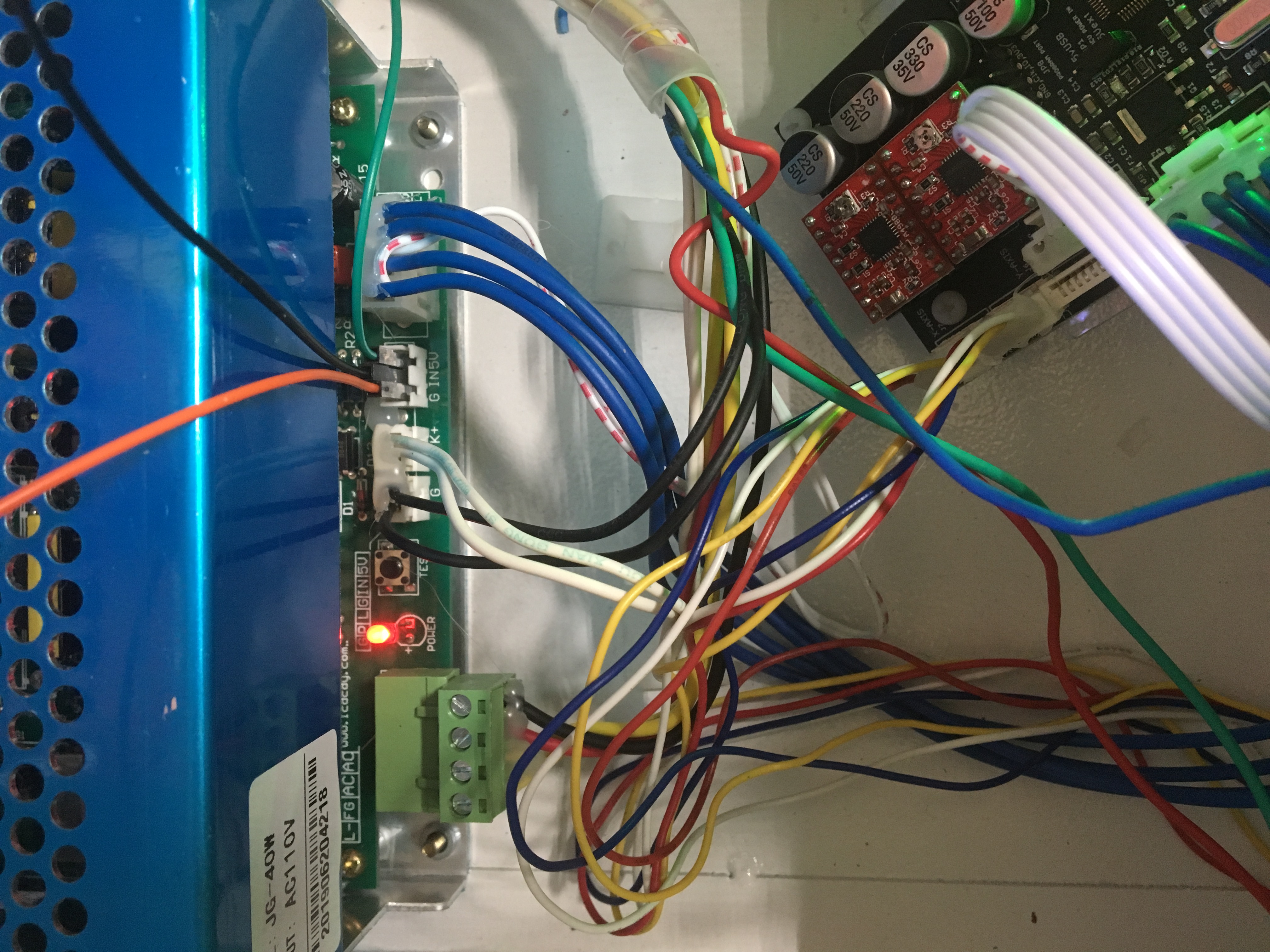
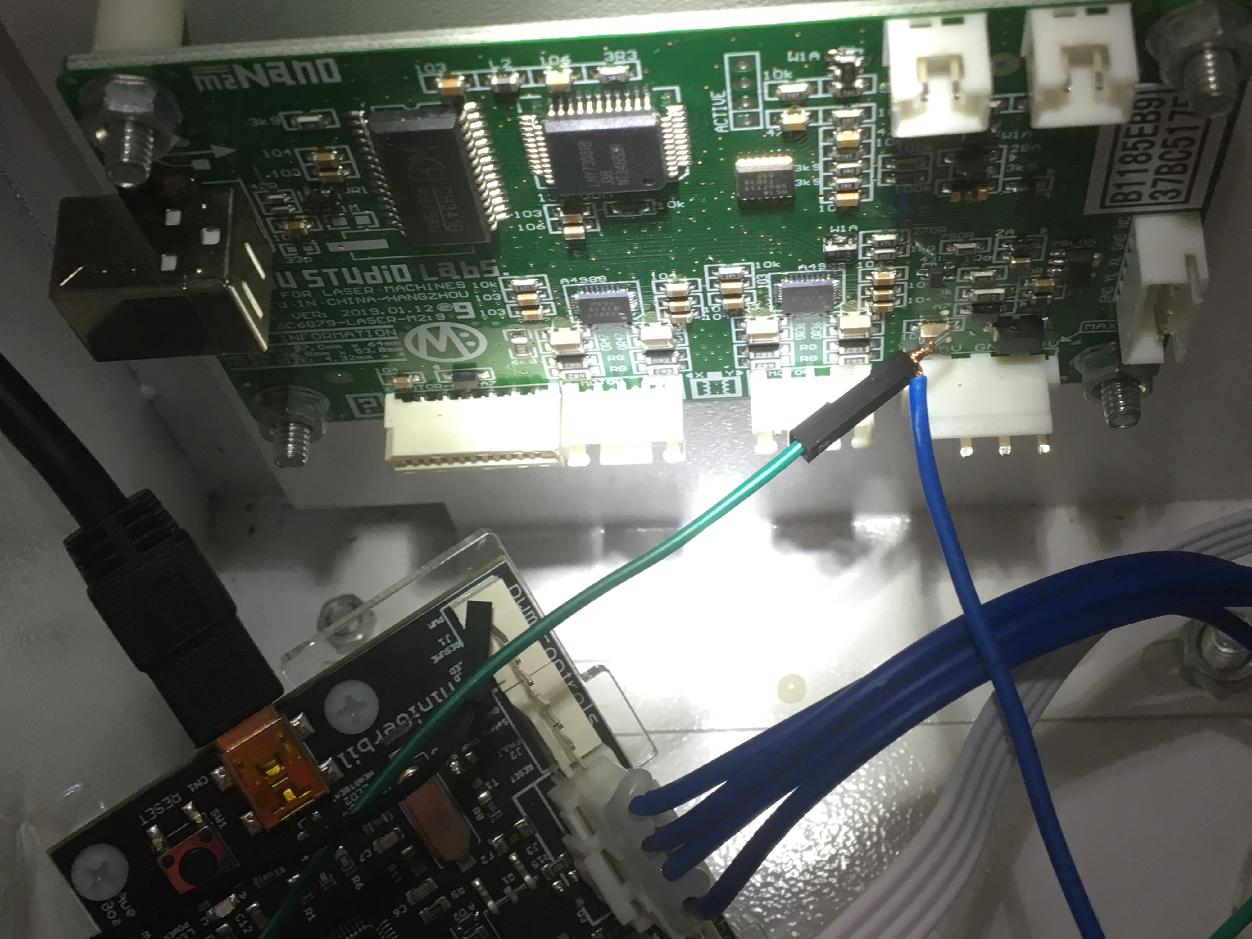
Is there a complete all in one place set of installation instructions for this combination of parts. PHOTOS INCLUDED
I have searched and looked and looked in the forum to no avail. Your online instructions do not show my combination of hardware or it is buried deep. Went to MG install video - wrong. Went to install written instructions - wrong. Found link to forum of supposedly my combo - wrong. If I can find the correct instructions I can probably get this thing going. All of the mechanical part appears to be working normal. But I have big problems with the laser and also can find no info on the correct workings of the two on board LEDs one green and one red. Laser fires full power at all times. No control with Potentiometer.
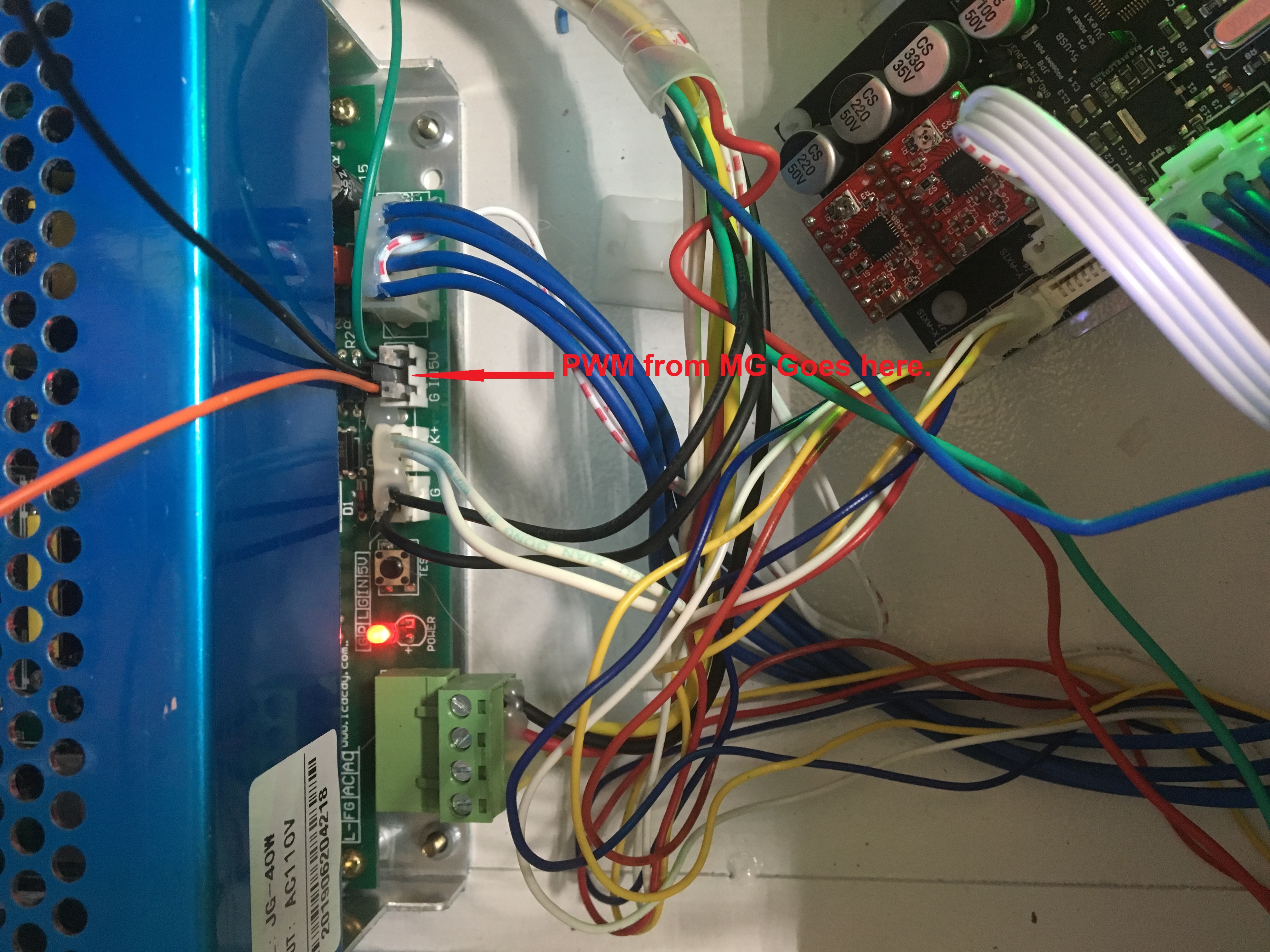
Instructions are very unclear on one forum posting. The customer asked EXACTLY how the 3 wire pwm connector on the power supply should be wired and never really got a clear answer (IMHO). Exactly how is that supposed to be wired. The answer he got was unplug it and put the green jumper on the IN pin and to PWM on MG. And then something about the GND already connected somewhere. OK - but what about the 5V pin. Wire - No Wire -- What? At this point I am totally frustrated. Instructions should be part of the Website and not pointed to a post in the forum. If I am mistaken and have overlooked the correct info for my combination of hardware, I ask forgiveness for this rant. If I am not, please point me to the correct instructions for my hardware. Photos included to let you see my connections on the PSU and my version of the MG. There have evidently been several versions with connectors in different places.
What I have: k49 with type 2 PSU and no ribbon cable. MiniGerbil purchased at the end of December 2019.
Is there a complete all in one place set of installation instructions for this combination of parts. PHOTOS INCLUDED
I have searched and looked and looked in the forum to no avail. Your online instructions do not show my combination of hardware or it is buried deep. Went to MG install video - wrong. Went to install written instructions - wrong. Found link to forum of supposedly my combo - wrong. If I can find the correct instructions I can probably get this thing going. All of the mechanical part appears to be working normal. But I have big problems with the laser and also can find no info on the correct workings of the two on board LEDs one green and one red. Laser fires full power at all times. No control with Potentiometer.
Instructions are very unclear on one forum posting. The customer asked EXACTLY how the 3 wire pwm connector on the power supply should be wired and never really got a clear answer (IMHO). Exactly how is that supposed to be wired. The answer he got was unplug it and put the green jumper on the IN pin and to PWM on MG. And then something about the GND already connected somewhere. OK - but what about the 5V pin. Wire - No Wire -- What? At this point I am totally frustrated. Instructions should be part of the Website and not pointed to a post in the forum. If I am mistaken and have overlooked the correct info for my combination of hardware, I ask forgiveness for this rant. If I am not, please point me to the correct instructions for my hardware. Photos included to let you see my connections on the PSU and my version of the MG. There have evidently been several versions with connectors in different places.
Uploaded files: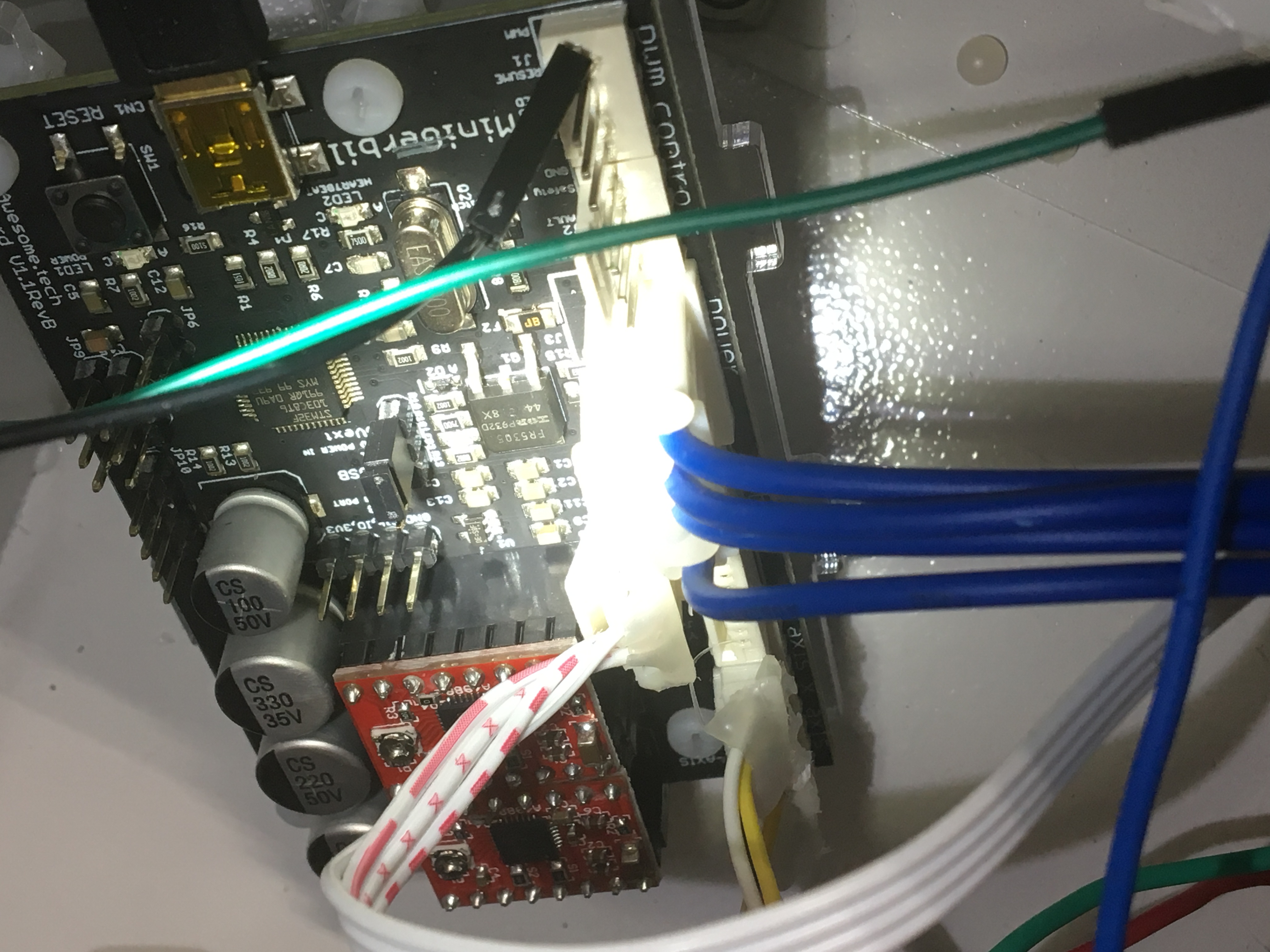
Quote from HumptyDumpty on January 5, 2020, 3:10 amI believe the instructions are the same just different connectors on different PSU. You need to disconnect the potentiometer from the IN pin and connect the MG PWM wire there. If you want to use the potentiometer at times you can with the addition of a SPDT switch so you don't have the pot and MG trying to control the IN pin at the same time. I found this somewhere on the site don't recall who contributed it or I'd give credit.
I believe the instructions are the same just different connectors on different PSU. You need to disconnect the potentiometer from the IN pin and connect the MG PWM wire there. If you want to use the potentiometer at times you can with the addition of a SPDT switch so you don't have the pot and MG trying to control the IN pin at the same time. I found this somewhere on the site don't recall who contributed it or I'd give credit.
Uploaded files:
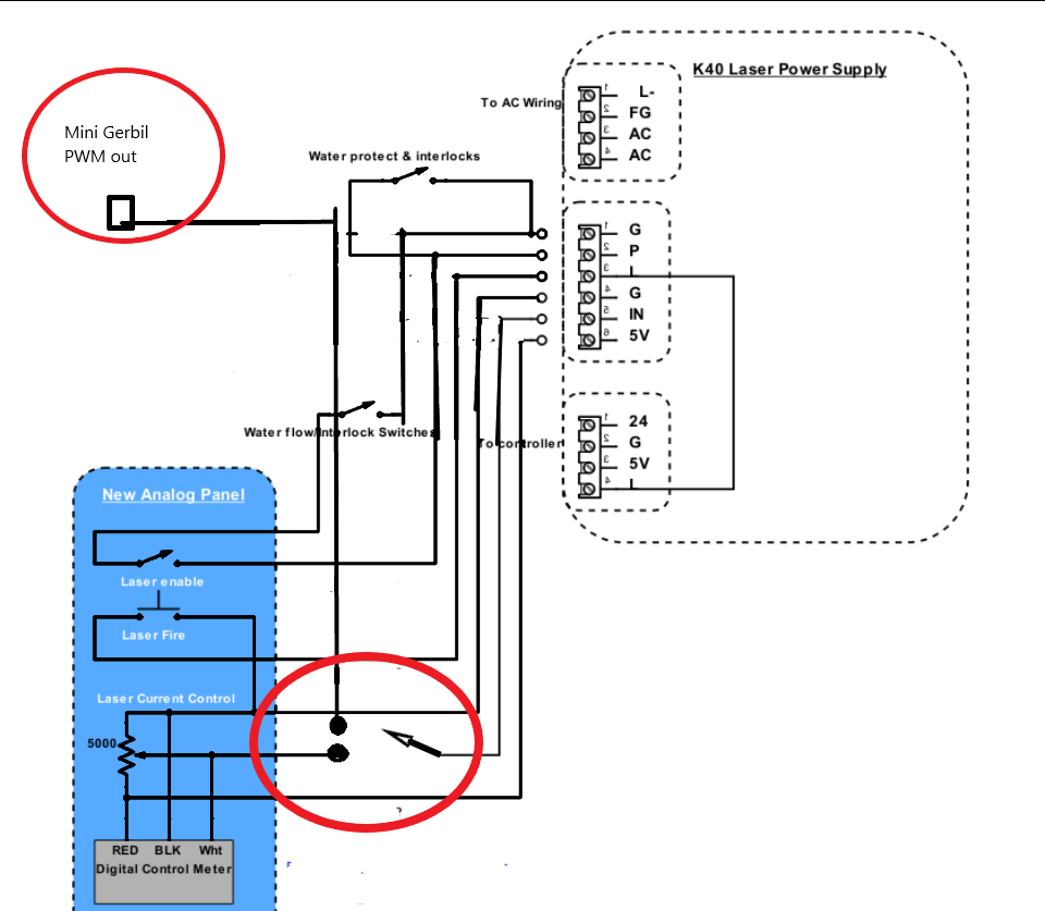
Quote from Paul on January 5, 2020, 9:11 amThe Gnd and 5V are already available in the Big Power Connector (4 pin connector) so they are redundant. On the K40 power supply they are repeated for the PWM plug (three pins) since they use in the analog version a potmeter which require 5V and Gnd to generate a valid reference point on the middle connection (output) of the potmeter.
Adding a identical 3 pin connector and wire would have driven up the cost of the controller. Hind sight is a nice thing, may be it is more cost effective to do so to reduce the number of these identical questions or support emails about this from customers... sigh.
The Gnd and 5V are already available in the Big Power Connector (4 pin connector) so they are redundant. On the K40 power supply they are repeated for the PWM plug (three pins) since they use in the analog version a potmeter which require 5V and Gnd to generate a valid reference point on the middle connection (output) of the potmeter.
Adding a identical 3 pin connector and wire would have driven up the cost of the controller. Hind sight is a nice thing, may be it is more cost effective to do so to reduce the number of these identical questions or support emails about this from customers... sigh.
Quote from dreiii on January 5, 2020, 9:33 amMr. DeGroot
I believe it would be safe to assume that most all of your customers, including me, are not electronic nerds or wizards. We live in a world of wood, plastic, metal, and other materials. Your board is advertised as "easy to install – simply follow the written and/or video instructions". And also "Full installation instructions and support provided". Also your reply did not to me did not answer any of my questions it only explained YOUR reasoning as to why the board is like it is. This does not help me when I cannot find an example of the wiring as it should be for my EXACT combination of hardware. Not my fault that your company and the Chinese keep changing and upgrading. Along with that should come "Full installation instructions" like you advertisement says. And where can I find (second request) information about the green, red and blue leds. I have searched your site for the simple word led and "no results".
Also your remarks about connectors on board and I quote: "Adding a identical 3 pin connector and wire would have driven up the cost of the controller. Hind sight is a nice thing, may be it is more cost effective to do so to reduce the number of these identical questions or support emails about this from customers... sigh."
It seems to me that something somewhere is lacking if there is that much confusion about the wiring of your product. Have you ever thought that perhaps you should go back and review your instructions and perhaps see where you ASSUME too much about your client base....... Big Big Sigh.
Mr. DeGroot
I believe it would be safe to assume that most all of your customers, including me, are not electronic nerds or wizards. We live in a world of wood, plastic, metal, and other materials. Your board is advertised as "easy to install – simply follow the written and/or video instructions". And also "Full installation instructions and support provided". Also your reply did not to me did not answer any of my questions it only explained YOUR reasoning as to why the board is like it is. This does not help me when I cannot find an example of the wiring as it should be for my EXACT combination of hardware. Not my fault that your company and the Chinese keep changing and upgrading. Along with that should come "Full installation instructions" like you advertisement says. And where can I find (second request) information about the green, red and blue leds. I have searched your site for the simple word led and "no results".
Also your remarks about connectors on board and I quote: "Adding a identical 3 pin connector and wire would have driven up the cost of the controller. Hind sight is a nice thing, may be it is more cost effective to do so to reduce the number of these identical questions or support emails about this from customers... sigh."
It seems to me that something somewhere is lacking if there is that much confusion about the wiring of your product. Have you ever thought that perhaps you should go back and review your instructions and perhaps see where you ASSUME too much about your client base....... Big Big Sigh.
Quote from dreiii on January 5, 2020, 9:36 amMany thanks to Humpty Dumpty who posted enough info that after several more tries, I "think" it might be working correctly. And then again maybe not. Maybe I can find out just exactly what the leds are telling me as they do not always act the same when going through the same procedure......sigh.
Many thanks to Humpty Dumpty who posted enough info that after several more tries, I "think" it might be working correctly. And then again maybe not. Maybe I can find out just exactly what the leds are telling me as they do not always act the same when going through the same procedure......sigh.