
K40d Mini Gerbil Wiring
Quote from gbzone on June 22, 2019, 4:34 amI have a K40d
I have extra wires on my controller both of the extra pairs of wires run to the power connector, nowhere else, if I leave these off the Mini Gerbil is just dead, where should they go?
Its the two black/red at the top
I have a K40d
I have extra wires on my controller both of the extra pairs of wires run to the power connector, nowhere else, if I leave these off the Mini Gerbil is just dead, where should they go?
Its the two black/red at the top
Uploaded files:
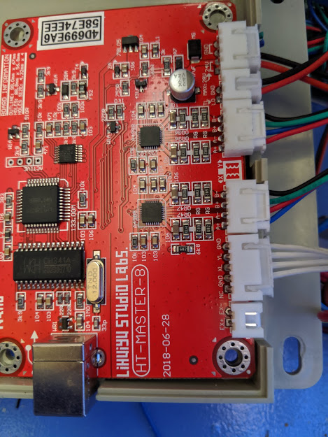
Quote from Paul on June 22, 2019, 9:17 amThanks for the photo, the silk screen on the board indicates that these are the 24DC (red) and Ground (black) power supply wires. We have not seen this model board. It seems LuHuiyu studio labs keeps changing their connectors and wonder if they make the boards for different manufacturers. Note: K40s are manufactured by many different factories in all kind of variants.
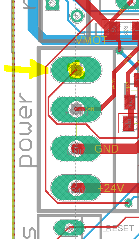
These two red/black wires go to the big (MTA156) power connector header on the mini Gerbil. The pins reading from left to right are:
LO (laser on), 5VDC, Ground, 24VDC (view towards the edge of the board, looking directly at the connectors).
The connectors on your board are different so ideally you should replace the connector (https://www.jaycar.com.au/4-pin-0-156-header-with-crimp-pins-3-96-pitch/p/HM3434)
or make a middle man part to bridge both connectors so you can always go back to the board if you need to.
The next pair of black and red wires, is the LO and ground. This switches the laser on and off. Note the black wires of LO and 24VDC are shared so you only need one black wire.
Hope this helps
Thanks for the photo, the silk screen on the board indicates that these are the 24DC (red) and Ground (black) power supply wires. We have not seen this model board. It seems LuHuiyu studio labs keeps changing their connectors and wonder if they make the boards for different manufacturers. Note: K40s are manufactured by many different factories in all kind of variants.
These two red/black wires go to the big (MTA156) power connector header on the mini Gerbil. The pins reading from left to right are:
LO (laser on), 5VDC, Ground, 24VDC (view towards the edge of the board, looking directly at the connectors).
The connectors on your board are different so ideally you should replace the connector (https://www.jaycar.com.au/4-pin-0-156-header-with-crimp-pins-3-96-pitch/p/HM3434)
or make a middle man part to bridge both connectors so you can always go back to the board if you need to.
The next pair of black and red wires, is the LO and ground. This switches the laser on and off. Note the black wires of LO and 24VDC are shared so you only need one black wire.
Hope this helps
Uploaded files:
Quote from gbzone on June 28, 2019, 9:58 amWell, so much for that, wired up as you said, gerbil lit up as it shorted on the connector, bye bye $86 plus the £20gbp + I had to pay in import duty... If anyone asks me I'll tell them to stay well clear of these boards. £100 out of pocket, Ragin!
Well, so much for that, wired up as you said, gerbil lit up as it shorted on the connector, bye bye $86 plus the £20gbp + I had to pay in import duty... If anyone asks me I'll tell them to stay well clear of these boards. £100 out of pocket, Ragin!
Quote from Paul on June 28, 2019, 12:55 pmHi, You have warranty on the board. Just return it and I will send you a replacement board via expedited courier. Just PM me for the address details and I will get it to you as soon as possible.
Hi, You have warranty on the board. Just return it and I will send you a replacement board via expedited courier. Just PM me for the address details and I will get it to you as soon as possible.
Quote from Paul on June 29, 2019, 9:59 amHi, no worries. Let me know the address details via a PM and I send a new controller on Monday. Also we can do a teamviewer session once you are installing it to ensure everything works out.
cheers, Paul
Hi, no worries. Let me know the address details via a PM and I send a new controller on Monday. Also we can do a teamviewer session once you are installing it to ensure everything works out.
cheers, Paul
Quote from gbzone on June 29, 2019, 10:55 pmCan you also look at the connector with 4 white wires on my board, I believe the 5v one is missing from mine, will I need a 5v feed here - my limit switches and mechanical
Can you also look at the connector with 4 white wires on my board, I believe the 5v one is missing from mine, will I need a 5v feed here - my limit switches and mechanical