
Help with installation 5v wire problem
Quote from Milos Pejakovic on December 20, 2022, 3:45 amHello, so im new to this and i dont have any experience with wires. Just few days ago i got my MG3 and im having trubble installing it. And would be great for someone who has some knowledge to help me out or im stuck with nano board and scrap MG3.
as shown in pictures i followed instructions from Awesome Tech but im missing 5v wire. I did few photos so someone who decide to help me have better understanding of my laser housing and power. Let me say that this is 50w laser 40cm x 40cm. please if we can chat on FB or Whatsapp or any other platform please lets do that because i can follow instructions way better than just typing. on FB you can text me: https://www.facebook.com/iApex555
on whatsapp: +38269222528 or Viber. Thanks alot for your time and help
Hello, so im new to this and i dont have any experience with wires. Just few days ago i got my MG3 and im having trubble installing it. And would be great for someone who has some knowledge to help me out or im stuck with nano board and scrap MG3.
as shown in pictures i followed instructions from Awesome Tech but im missing 5v wire. I did few photos so someone who decide to help me have better understanding of my laser housing and power. Let me say that this is 50w laser 40cm x 40cm. please if we can chat on FB or Whatsapp or any other platform please lets do that because i can follow instructions way better than just typing. on FB you can text me: https://www.facebook.com/iApex555
on whatsapp: +38269222528 or Viber. Thanks alot for your time and help
Quote from dancolwp1974 on December 20, 2022, 9:44 pmHi Milos,
it's late here so just a quick response:
Check out these pins - you would need just a single one of them to slide into the 4 pin plastic housing. In practice you should be say 5 so you have some spare.
https://www.mouser.com/ProductDetail/538-08-50-0106
I appreciate you've uploaded all the photos, but it's hard for someone online to trace from photo to photo. I'll draw a circuit diagram tomorrow of how you should hook everything up. Once again, I urge you to find a local person who can physically inspect and point to wires, it's honestly going to be easier. Maybe ask these guys for assistance? https://montenegromakers.me/
Regards,
Dan
Hi Milos,
it's late here so just a quick response:
Check out these pins - you would need just a single one of them to slide into the 4 pin plastic housing. In practice you should be say 5 so you have some spare.
https://www.mouser.com/ProductDetail/538-08-50-0106
I appreciate you've uploaded all the photos, but it's hard for someone online to trace from photo to photo. I'll draw a circuit diagram tomorrow of how you should hook everything up. Once again, I urge you to find a local person who can physically inspect and point to wires, it's honestly going to be easier. Maybe ask these guys for assistance? https://montenegromakers.me/
Regards,
Dan
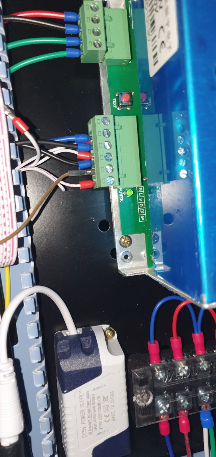
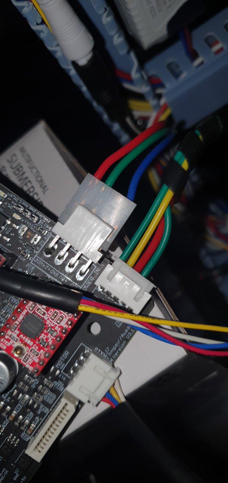
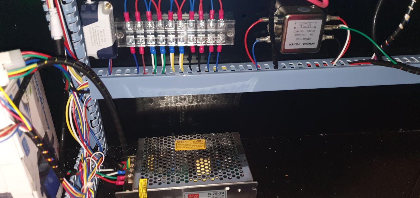
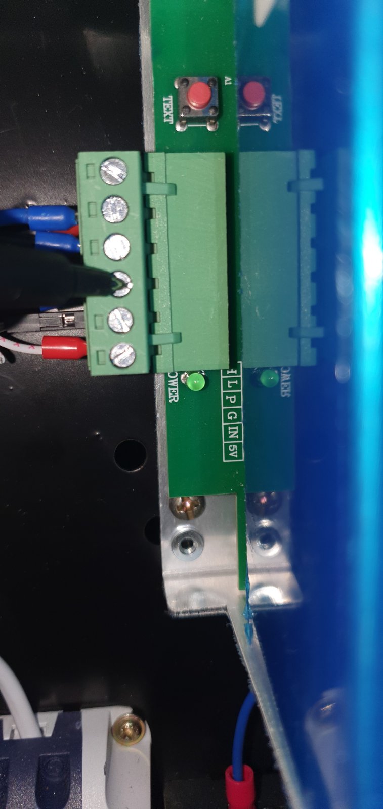
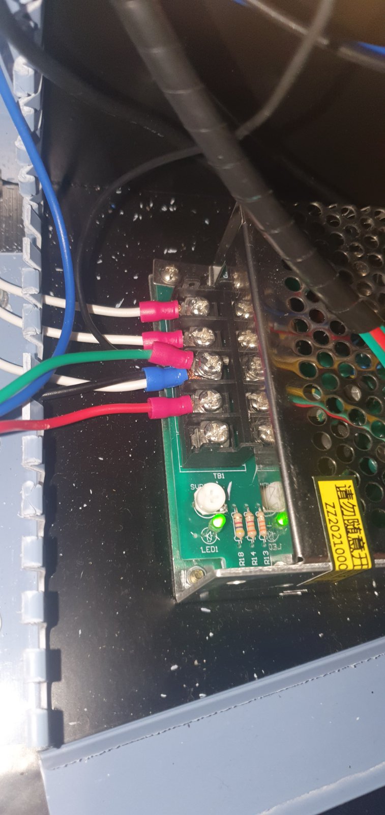
Quote from Milos Pejakovic on December 21, 2022, 4:30 amHello Dan, i understand that i need Molex connector but question is from should i take 5v so it will work. is it directly from Power supply shown in picture no. 1? i marked with yellow pointer.
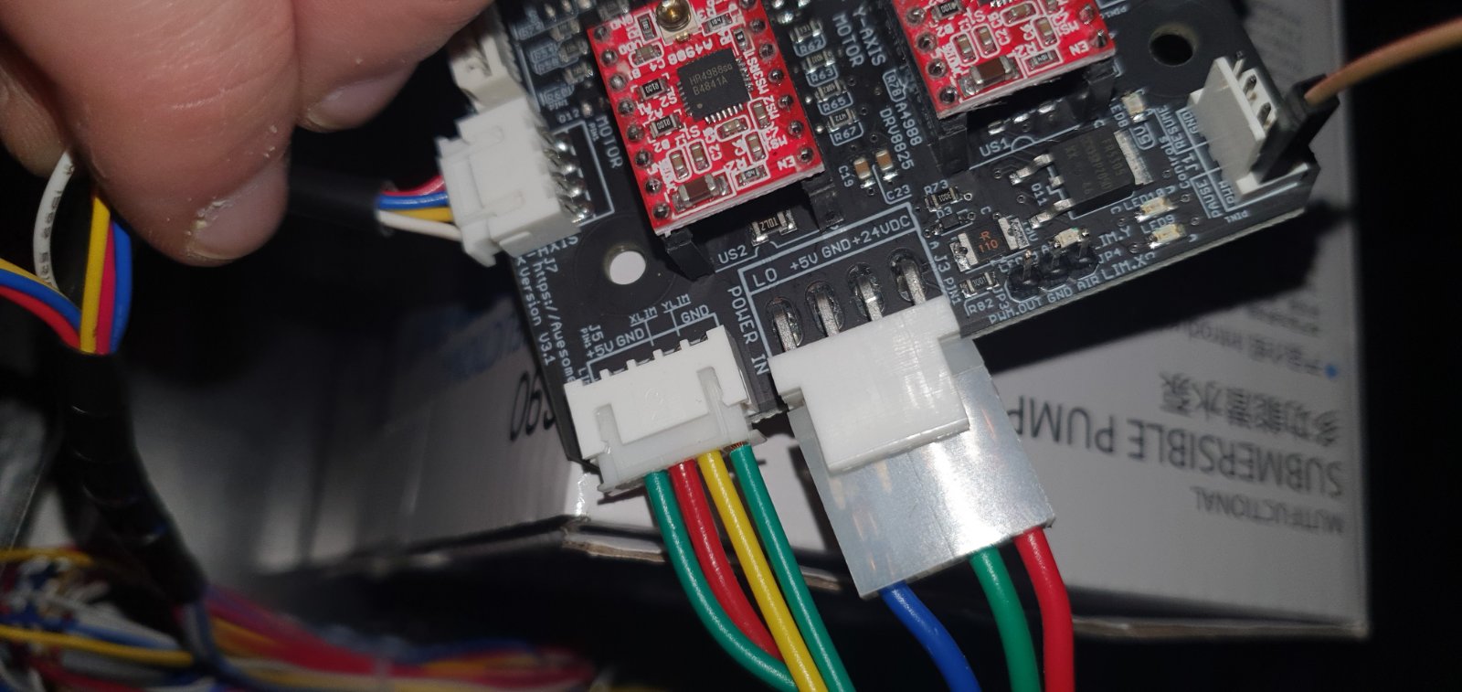
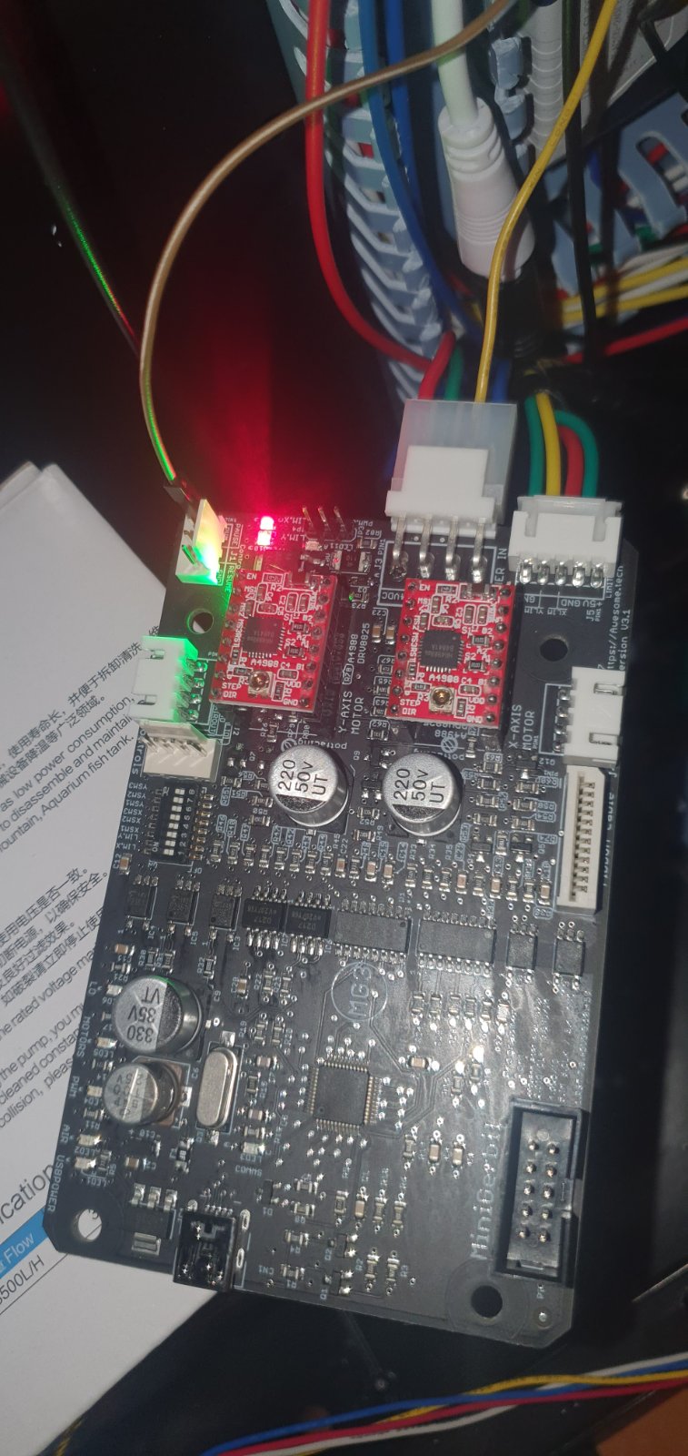
and if so do i need someting else to go with it or i can just do wire to connector on MG3?
shown in picture no. 2
about https://montenegromakers.me/ they are not duing this kind of work...
Hello Dan, i understand that i need Molex connector but question is from should i take 5v so it will work. is it directly from Power supply shown in picture no. 1? i marked with yellow pointer.
and if so do i need someting else to go with it or i can just do wire to connector on MG3?
shown in picture no. 2
about https://montenegromakers.me/ they are not duing this kind of work...
Uploaded files:
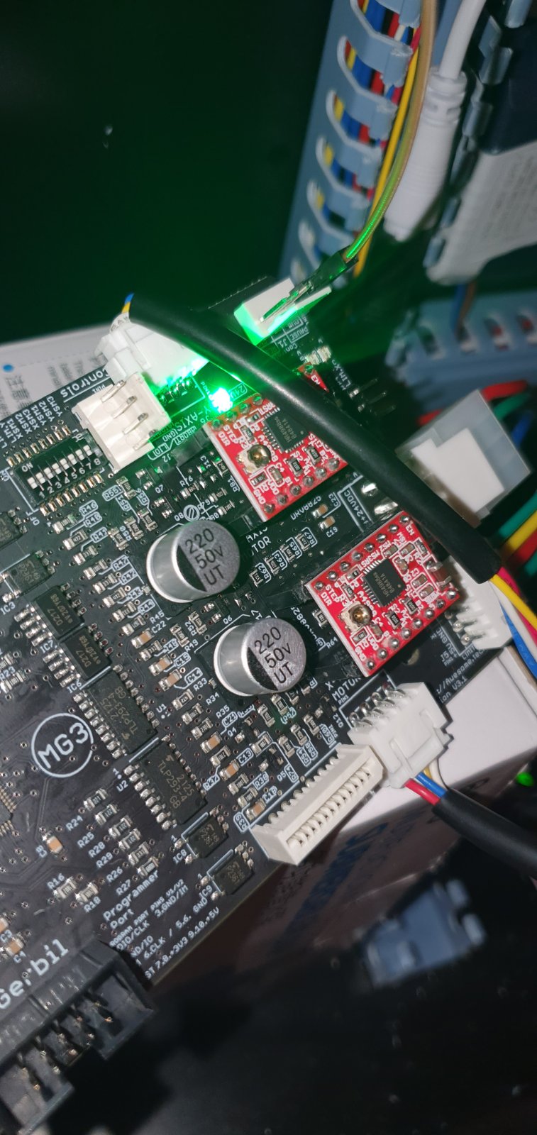
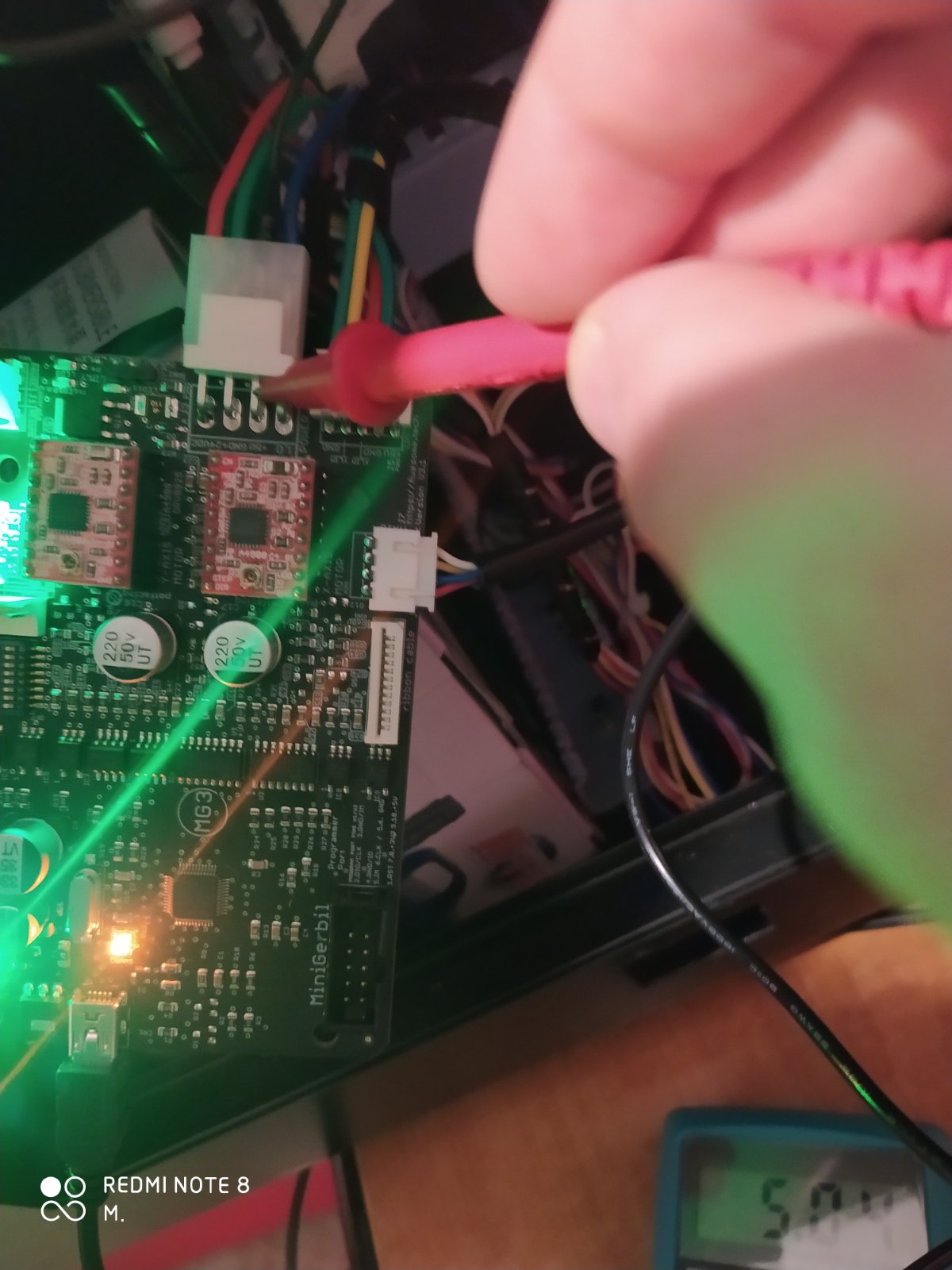
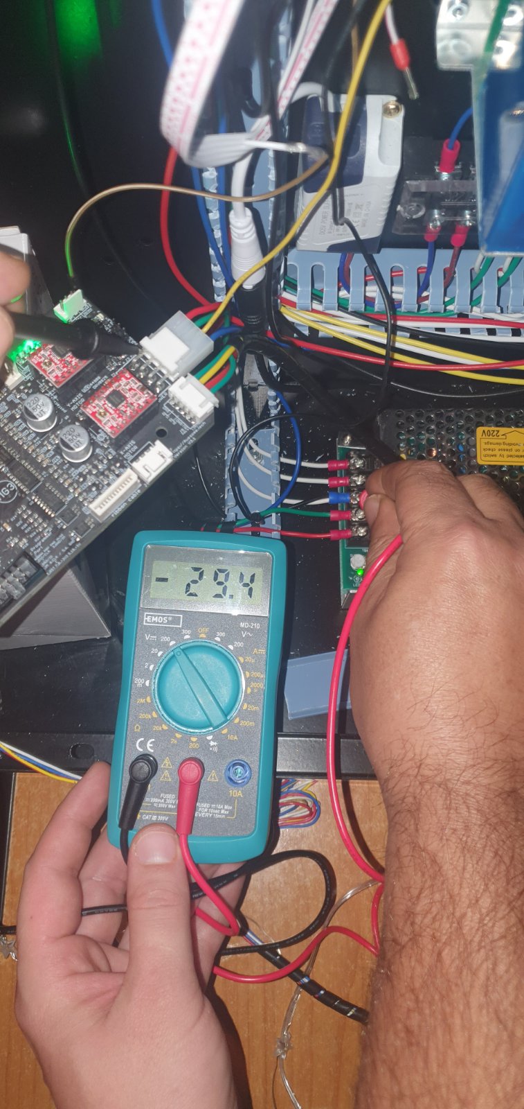
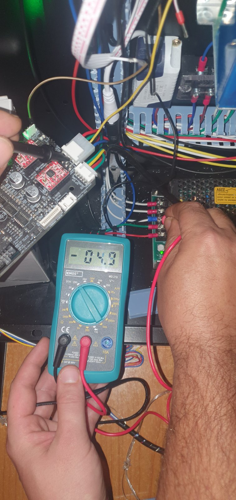
Quote from Milos Pejakovic on December 21, 2022, 5:31 amHello Dan so i was talking with one of the electricians and he told me what i can do to connect 5v from PSU and go to Molex jack and test is 5v going to controller as you can see its tested and 5.03 - 5.04v is going to controller but on controller green light that shows that 5v is present its not lightning up at all. and in lightburn on PC its says the same thing.
Hello Dan so i was talking with one of the electricians and he told me what i can do to connect 5v from PSU and go to Molex jack and test is 5v going to controller as you can see its tested and 5.03 - 5.04v is going to controller but on controller green light that shows that 5v is present its not lightning up at all. and in lightburn on PC its says the same thing.
Uploaded files: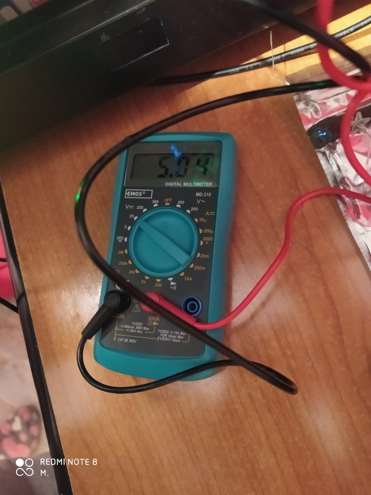
Quote from dancolwp1974 on December 22, 2022, 11:10 amHi Milos,
your photo shows a multimeter with a red probe, but I need to know where the black probe is connected ! Please advise.
I'm unsure if you know the concept of a common ground, please advise.
Before making any connections, ensure you turn off all power, and do not connect to any mains connections, even if they are labelled GND.
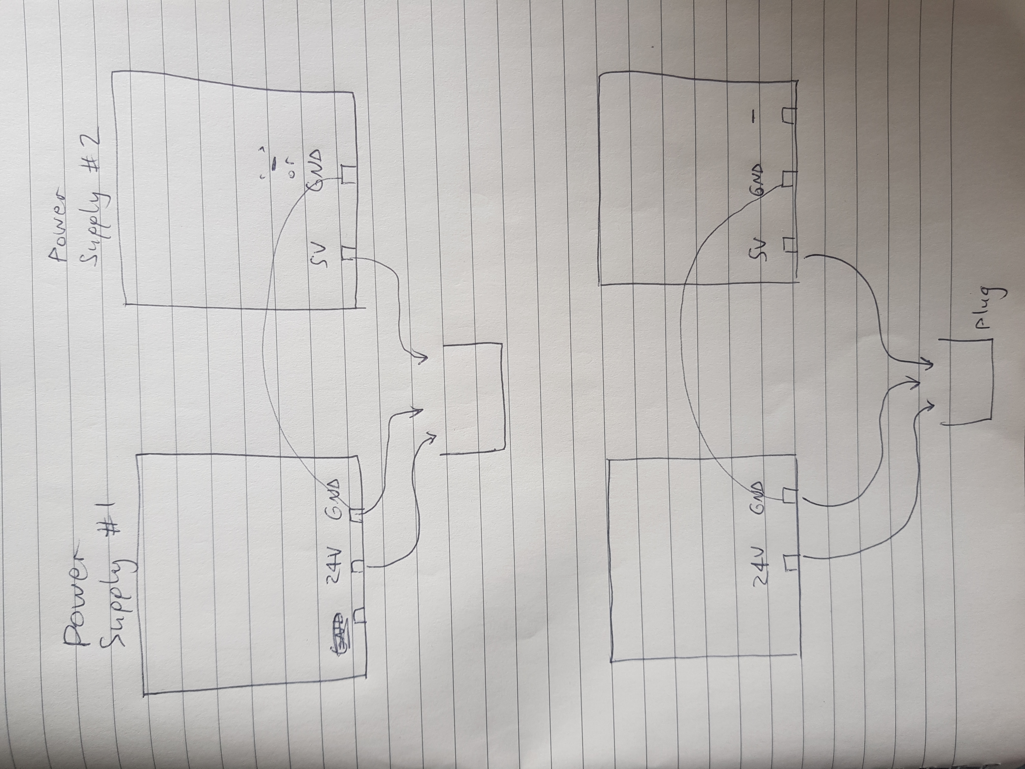
In the image below, the top diagram shows that if you have a 5V supply with a +5V and EITHER a Ground or - terminal, then you connect everything as shown. The molex plug at the bottom of the diagram is just a conceptual indication, stick to the existing pin layout of course.
OR, if your 5V supply has a +5V and a GND AND a separate - terminal, then connect as shown in the bottom diagram.
Regards,
Dan
Hi Milos,
your photo shows a multimeter with a red probe, but I need to know where the black probe is connected ! Please advise.
I'm unsure if you know the concept of a common ground, please advise.
Before making any connections, ensure you turn off all power, and do not connect to any mains connections, even if they are labelled GND.
In the image below, the top diagram shows that if you have a 5V supply with a +5V and EITHER a Ground or - terminal, then you connect everything as shown. The molex plug at the bottom of the diagram is just a conceptual indication, stick to the existing pin layout of course.
OR, if your 5V supply has a +5V and a GND AND a separate - terminal, then connect as shown in the bottom diagram.
Regards,
Dan
Uploaded files:
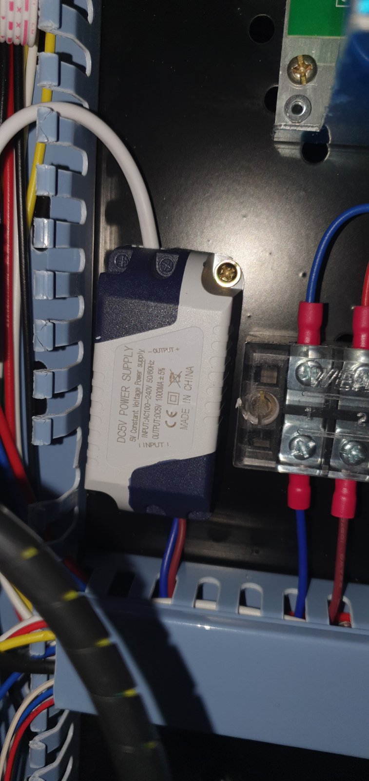
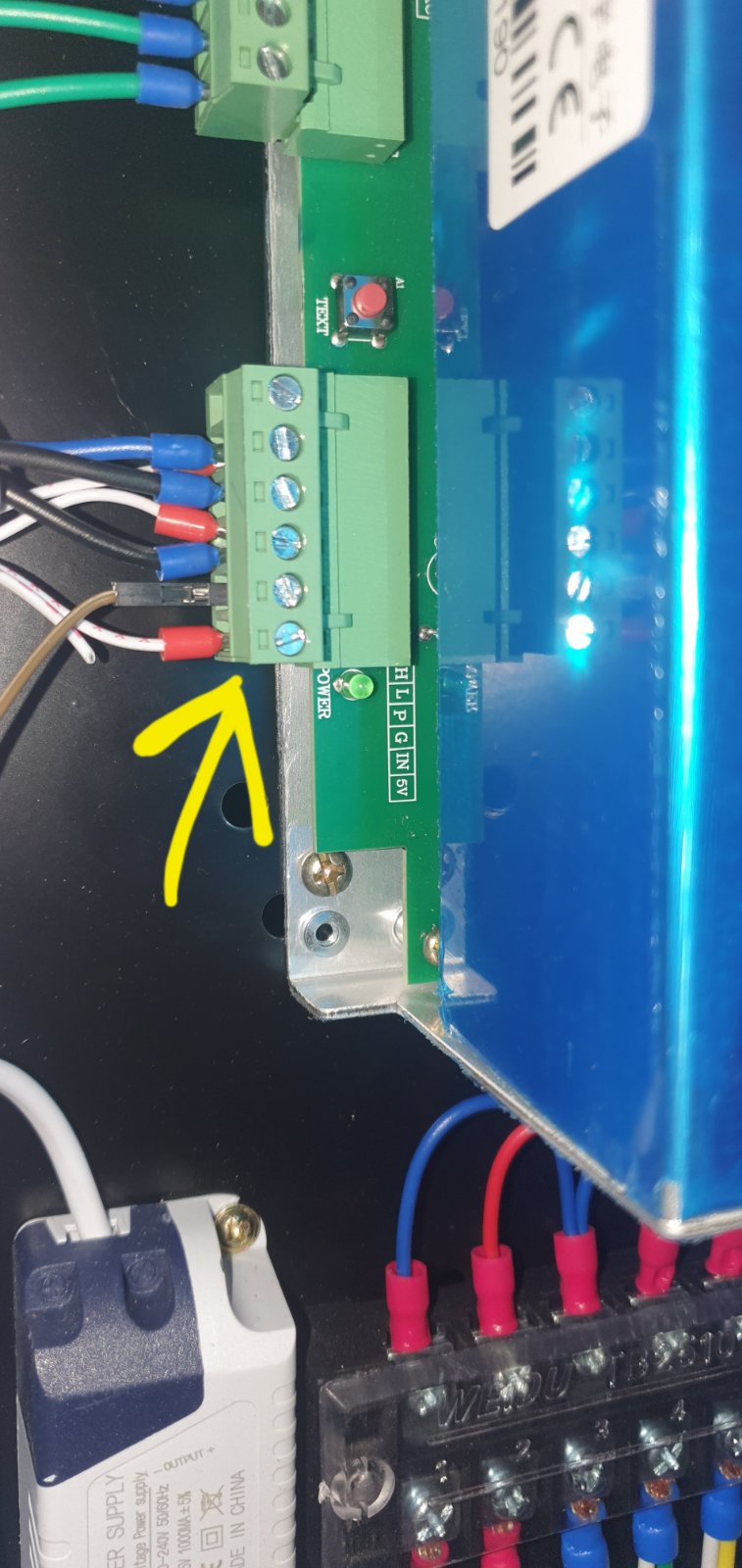
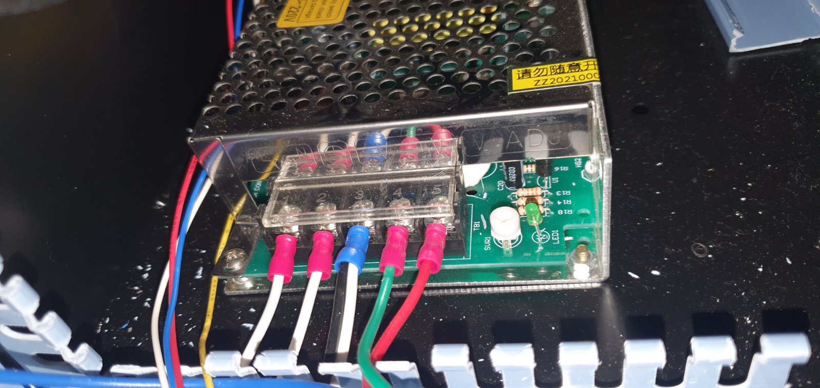
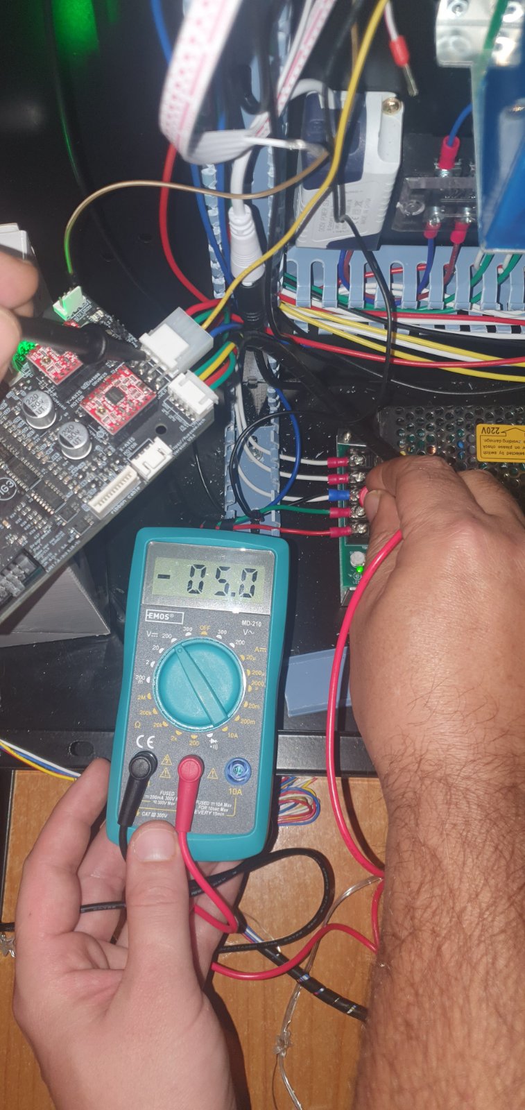
Quote from Milos Pejakovic on December 23, 2022, 6:02 amHello Dan, so first of all pic no.1 is black probe that i forgot to show you.
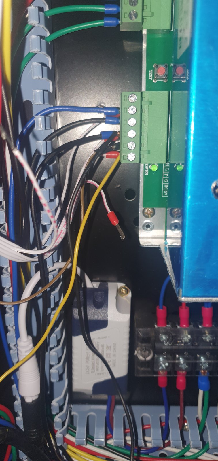
no.2 pic show second power supply. but i cant find 5v wire. im sending this picture so maybe you understand this second powersuply better because it seeems i cant find 5v from it.
Hello Dan, so first of all pic no.1 is black probe that i forgot to show you.
no.2 pic show second power supply. but i cant find 5v wire. im sending this picture so maybe you understand this second powersuply better because it seeems i cant find 5v from it.
Quote from Milos Pejakovic on December 23, 2022, 6:05 amthis is side picture of second powersupply. it seems i dont understand anything. even my father who knows about wires he dont understad this...
this is side picture of second powersupply. it seems i dont understand anything. even my father who knows about wires he dont understad this...
Uploaded files: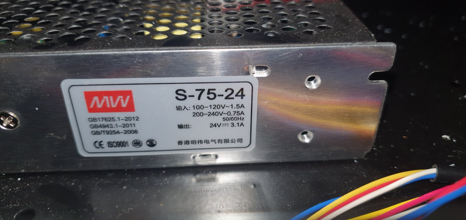
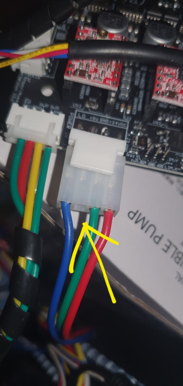
Quote from Milos Pejakovic on December 24, 2022, 5:28 amHi Dan so can you please elaborate this: when i make connection as you showed i make 5v but lose 24v. I BEG YOU to please tell me can i make video or something for you to see this clearly so you can help me out here i am after 15days after purchase of MG3 and i cant use it im desperate that i just throw away 150euros for nothing.
Hi Dan so can you please elaborate this: when i make connection as you showed i make 5v but lose 24v. I BEG YOU to please tell me can i make video or something for you to see this clearly so you can help me out here i am after 15days after purchase of MG3 and i cant use it im desperate that i just throw away 150euros for nothing.
Uploaded files: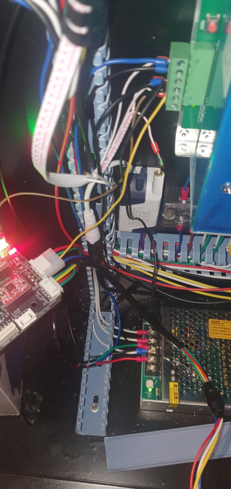

Quote from dancolwp1974 on December 24, 2022, 8:58 amHi Milos,
thanks for the updated photos.
Let's have a video meeting, do you use WhatsApp?
I'll email you privately and we can share details.
In the mean time I will consider your latest photos and message and write a response.
Regards,
Dan
Hi Milos,
thanks for the updated photos.
Let's have a video meeting, do you use WhatsApp?
I'll email you privately and we can share details.
In the mean time I will consider your latest photos and message and write a response.
Regards,
Dan
Quote from dancolwp1974 on December 24, 2022, 2:29 pmHi Milos,
Thanks for the photos, I can see the problem now:
The blue power supply you have has a 5V logic level output, but as you've already unsuccessfully tried to power the controller via the yellow wire, then it is not designed for powering a circuit. The purpose of the blue power supply is to create a 22kV high voltage output to operate the laser.
The second power supply (silver) you have clearly says it outputs 24V. It has no 5V output. Its purpose is to power the motors.
You need to buy a cheap 5V power supply, and connect it as shown in the hand drawn diagram above. Its purpose is to power the electronics. That should work fine.
Regards,
Dan
Hi Milos,
Thanks for the photos, I can see the problem now:
The blue power supply you have has a 5V logic level output, but as you've already unsuccessfully tried to power the controller via the yellow wire, then it is not designed for powering a circuit. The purpose of the blue power supply is to create a 22kV high voltage output to operate the laser.
The second power supply (silver) you have clearly says it outputs 24V. It has no 5V output. Its purpose is to power the motors.
You need to buy a cheap 5V power supply, and connect it as shown in the hand drawn diagram above. Its purpose is to power the electronics. That should work fine.
Regards,
Dan
Quote from HumptyDumpty on December 28, 2022, 7:18 amThere is no common DC ground between the two power supplies. And in a couple photos it looks like the DC ground is connected to mains ground on the 24V PS. With the 24V PS connected to the mg3 board and the yellow wire running from the LPS 5V he's testing with a multimeter at the LPS ground terminal with the negative probe and at the board with the positive probe (Need to test at the board with both probes). The ground wire the board has connected is from the 24V PS so the board does not get the 5V from the LPS.
There is no common DC ground between the two power supplies. And in a couple photos it looks like the DC ground is connected to mains ground on the 24V PS. With the 24V PS connected to the mg3 board and the yellow wire running from the LPS 5V he's testing with a multimeter at the LPS ground terminal with the negative probe and at the board with the positive probe (Need to test at the board with both probes). The ground wire the board has connected is from the 24V PS so the board does not get the 5V from the LPS.
Quote from dancolwp1974 on December 28, 2022, 10:16 amThanks HumptyDumpty. Milos and I ended up having a productive call over WhatsApp and action is on himto purchase a standalone 5V supply and we'll go from there
Thanks HumptyDumpty. Milos and I ended up having a productive call over WhatsApp and action is on himto purchase a standalone 5V supply and we'll go from there