
Help with installation
Quote from Milos Pejakovic on November 30, 2022, 7:27 amHello first off all let me say im new to this. And would be more than happy if someone could help me instal my minigrebil 3 to this m2 nano 50w laser. I see my PSU is not the same as shown in video so if someone could help please do. Thanks. I've taken 4 photos of inside of machine i hope that is ok if i need to take more please say so i can give more info.
Hello first off all let me say im new to this. And would be more than happy if someone could help me instal my minigrebil 3 to this m2 nano 50w laser. I see my PSU is not the same as shown in video so if someone could help please do. Thanks. I've taken 4 photos of inside of machine i hope that is ok if i need to take more please say so i can give more info.
Uploaded files: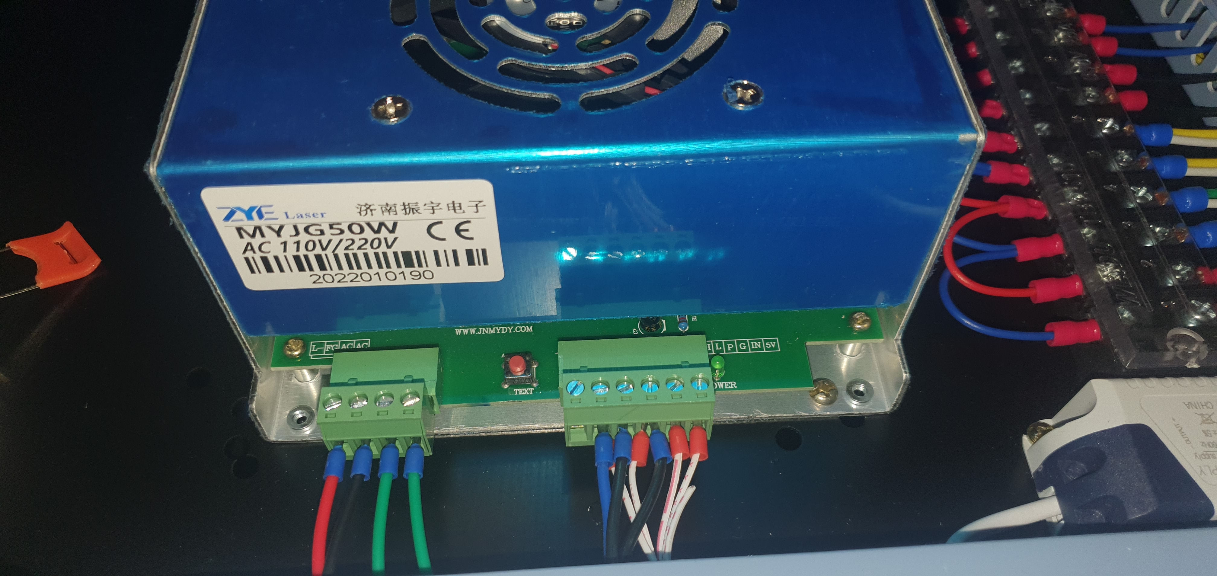
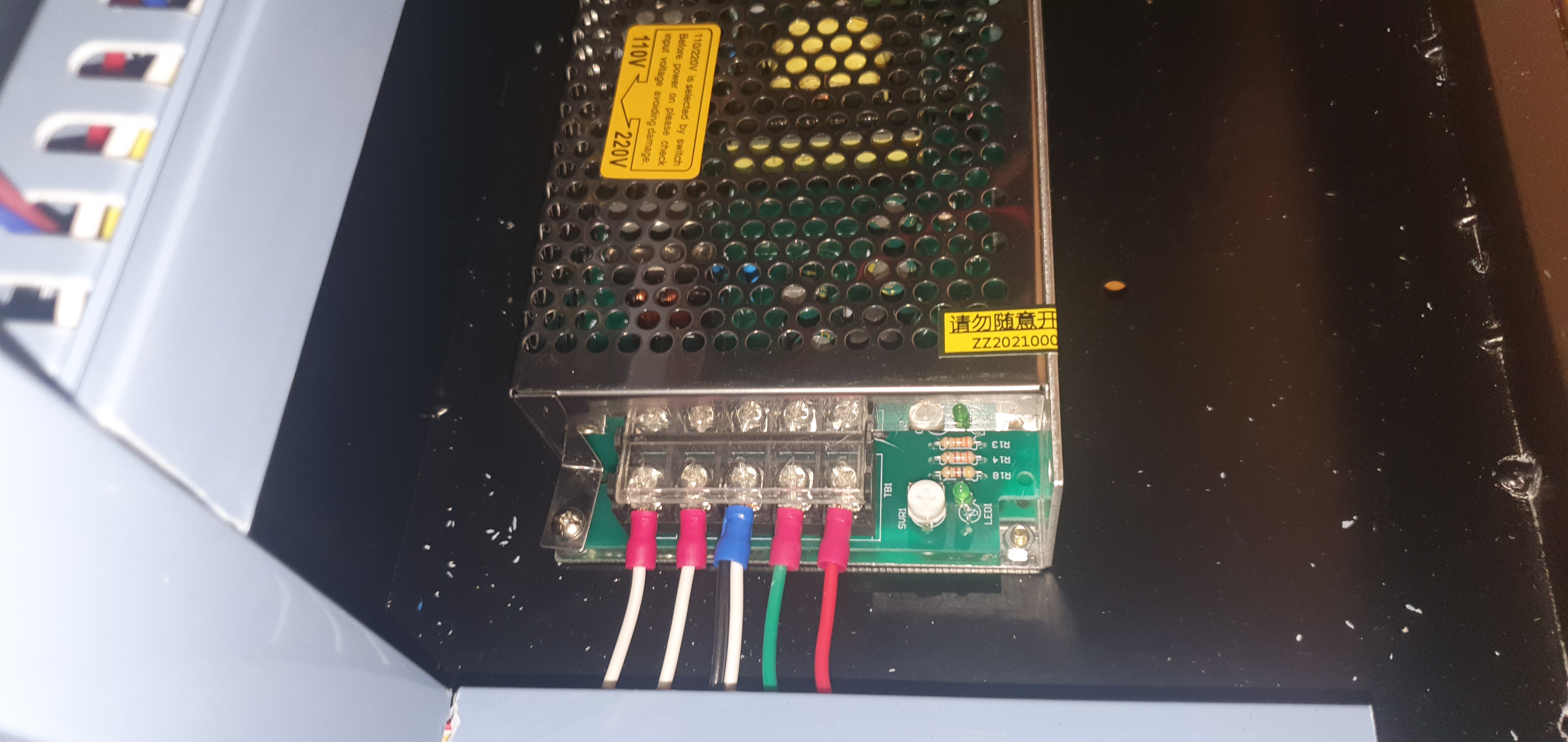
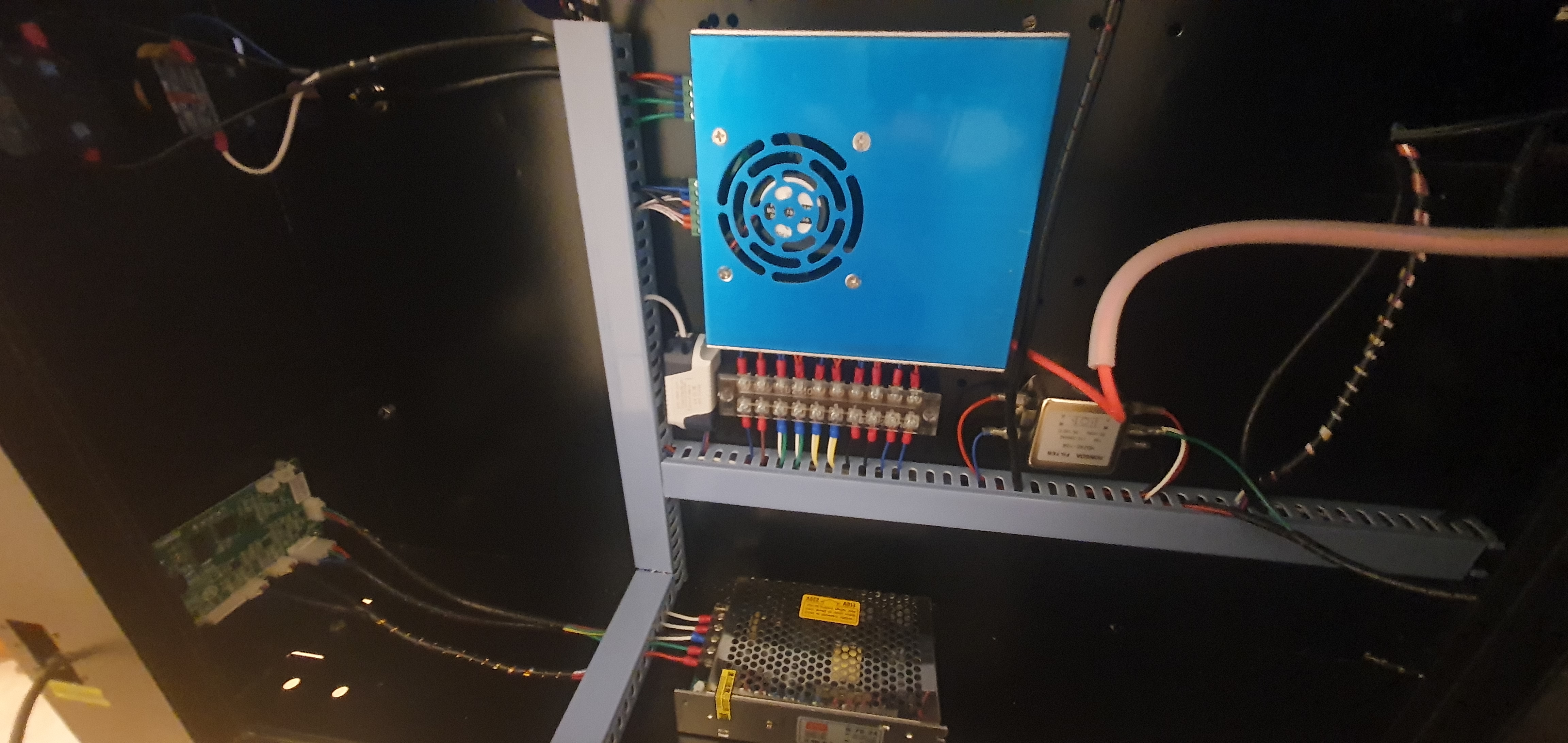
Quote from Paul on December 1, 2022, 8:55 amHi Milos, thanks for reaching out to us. The PSU is not the same but still can be used with the MG3. The 4 Pin terminal is the mains terminal and you don't have to do anything with that connector. Just leave it as it is.
You just need to use the lower 6 pin terminal. The label on the PCB tells you what the screw terminals are for. I can see L, P, G, IN and 5V. The first screw terminal label is not visible but I guess it says H and it's not wired anyway.
These Labels are connected as following
L - is your LO signal (enable laser), goes to the corresponding LO terminal pin on the big 4 pin connector on the MG3.
P- protect (connected to the switch on the control panel of the laser case). Needs to go to G via the switch to enable the laser. If that never happens, you can wire this to G to test the machine.
G - Ground - goes to the corresponding GND pin on the big 4 pin connector on the MG3.
IN - your laser strength signal. Disconnect the existing wires (isolate and tape them up). Connect to the MG3 IN terminal (PWM signal)
5V - reference signal. goes to the corresponding 5V pin on the big 4 pin connector on the MG3.
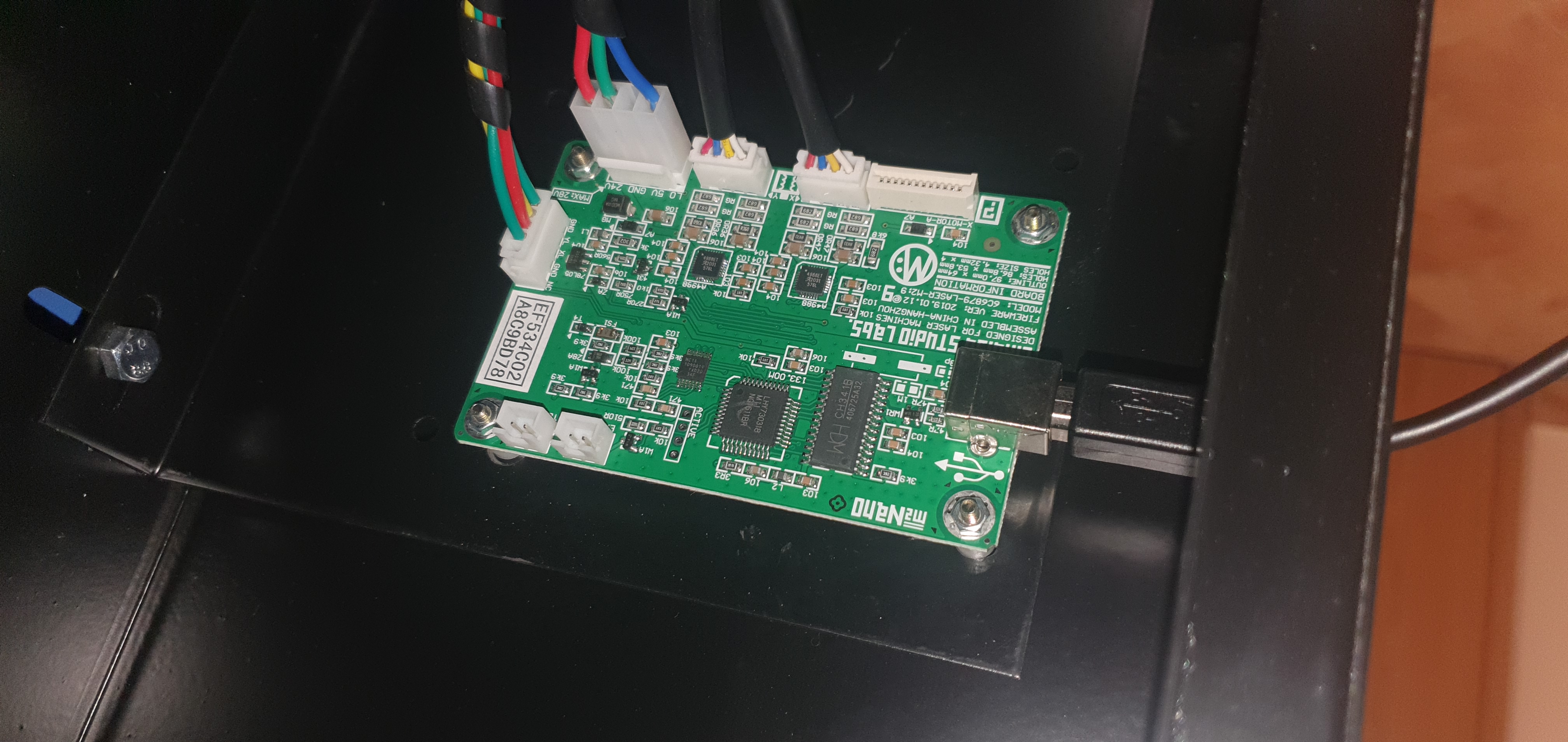
Nano board connectors:
The motor connectors labelled X and Y can go directly to the corresponding 4 pin motor connectors.
The Big 4 pin connector goes to the big 4 pin connector on the MG3. Note the orientation LO, 5V, GND, 24V. 5V wire is not there which is fine since we use the 5V wire from the PSU. LO is a blue wire and check if it's wired to the PSU on screw terminal L. If so then you don't need to wire LO separately as I described in the PSU part above. If not wired then remove the blue wire from the connector, isolate it and tape it up. Connect a wire from terminal L on the PSU to LO on the MG 3. Note you can remove the prongs from the connector via a small instrument screw driver by pushing in a tiny lip to relieve the prong from its position and pulling at the wire at the same time.
Finally you locate the 5 pin connector on the Nano board with labels Gnd, YL,XL,GND, NC (limits Y, X and Ground). This should go to the limit pin header on the MG3. Note the orientation via the first pin GND. It seems your limit switches are wired independently (no share common ground) and are mechanical, so no 5V line required. You can check the limit switches via a multimeter on the Ohm range and via the MG3 console in Lightburn by issuing the question command (enter ? symbol in the console). It should show the Pn:X,Y status when they are hit. They are normally closed switches which open when hit. If not you can re-solder the wires on the limit switches from the NO pin to the appropriate NC switch pin or invert the limit switches via $ setting $5 (use lightburn console and enter $5=0).
Test the directions of the motor, if wrong, set the $ settings for motor $3), test the homing.( see https://awesome.tech/what-are-settings/ ) Note the $3 uses a mask X=bit0, Y=bit1, 0=both one direction, 1=x other direction then Y, 2 Y other direction then X, 3 both x and y other direction.
Hope this helps! Let us know how it went and if required we help you further.
Cheers, Paul
Hi Milos, thanks for reaching out to us. The PSU is not the same but still can be used with the MG3. The 4 Pin terminal is the mains terminal and you don't have to do anything with that connector. Just leave it as it is.
You just need to use the lower 6 pin terminal. The label on the PCB tells you what the screw terminals are for. I can see L, P, G, IN and 5V. The first screw terminal label is not visible but I guess it says H and it's not wired anyway.
These Labels are connected as following
L - is your LO signal (enable laser), goes to the corresponding LO terminal pin on the big 4 pin connector on the MG3.
P- protect (connected to the switch on the control panel of the laser case). Needs to go to G via the switch to enable the laser. If that never happens, you can wire this to G to test the machine.
G - Ground - goes to the corresponding GND pin on the big 4 pin connector on the MG3.
IN - your laser strength signal. Disconnect the existing wires (isolate and tape them up). Connect to the MG3 IN terminal (PWM signal)
5V - reference signal. goes to the corresponding 5V pin on the big 4 pin connector on the MG3.
Nano board connectors:
The motor connectors labelled X and Y can go directly to the corresponding 4 pin motor connectors.
The Big 4 pin connector goes to the big 4 pin connector on the MG3. Note the orientation LO, 5V, GND, 24V. 5V wire is not there which is fine since we use the 5V wire from the PSU. LO is a blue wire and check if it's wired to the PSU on screw terminal L. If so then you don't need to wire LO separately as I described in the PSU part above. If not wired then remove the blue wire from the connector, isolate it and tape it up. Connect a wire from terminal L on the PSU to LO on the MG 3. Note you can remove the prongs from the connector via a small instrument screw driver by pushing in a tiny lip to relieve the prong from its position and pulling at the wire at the same time.
Finally you locate the 5 pin connector on the Nano board with labels Gnd, YL,XL,GND, NC (limits Y, X and Ground). This should go to the limit pin header on the MG3. Note the orientation via the first pin GND. It seems your limit switches are wired independently (no share common ground) and are mechanical, so no 5V line required. You can check the limit switches via a multimeter on the Ohm range and via the MG3 console in Lightburn by issuing the question command (enter ? symbol in the console). It should show the Pn:X,Y status when they are hit. They are normally closed switches which open when hit. If not you can re-solder the wires on the limit switches from the NO pin to the appropriate NC switch pin or invert the limit switches via $ setting $5 (use lightburn console and enter $5=0).
Test the directions of the motor, if wrong, set the $ settings for motor $3), test the homing.( see https://awesome.tech/what-are-settings/ ) Note the $3 uses a mask X=bit0, Y=bit1, 0=both one direction, 1=x other direction then Y, 2 Y other direction then X, 3 both x and y other direction.
Hope this helps! Let us know how it went and if required we help you further.
Cheers, Paul
Quote from Milos Pejakovic on December 4, 2022, 2:59 amQuote from Paul on December 1, 2022, 8:55 amHi Milos, thanks for reaching out to us. The PSU is not the same but still can be used with the MG3. The 4 Pin terminal is the mains terminal and you don't have to do anything with that connector. Just leave it as it is.
You just need to use the lower 6 pin terminal. The label on the PCB tells you what the screw terminals are for. I can see L, P, G, IN and 5V. The first screw terminal label is not visible but I guess it says H and it's not wired anyway.
These Labels are connected as following
L - is your LO signal (enable laser), goes to the corresponding LO terminal pin on the big 4 pin connector on the MG3.
P- protect (connected to the switch on the control panel of the laser case). Needs to go to G via the switch to enable the laser. If that never happens, you can wire this to G to test the machine.
G - Ground - goes to the corresponding GND pin on the big 4 pin connector on the MG3.
IN - your laser strength signal. Disconnect the existing wires (isolate and tape them up). Connect to the MG3 IN terminal (PWM signal)
5V - reference signal. goes to the corresponding 5V pin on the big 4 pin connector on the MG3.
Nano board connectors:
The motor connectors labelled X and Y can go directly to the corresponding 4 pin motor connectors.
The Big 4 pin connector goes to the big 4 pin connector on the MG3. Note the orientation LO, 5V, GND, 24V. 5V wire is not there which is fine since we use the 5V wire from the PSU. LO is a blue wire and check if it's wired to the PSU on screw terminal L. If so then you don't need to wire LO separately as I described in the PSU part above. If not wired then remove the blue wire from the connector, isolate it and tape it up. Connect a wire from terminal L on the PSU to LO on the MG 3. Note you can remove the prongs from the connector via a small instrument screw driver by pushing in a tiny lip to relieve the prong from its position and pulling at the wire at the same time.
Finally you locate the 5 pin connector on the Nano board with labels Gnd, YL,XL,GND, NC (limits Y, X and Ground). This should go to the limit pin header on the MG3. Note the orientation via the first pin GND. It seems your limit switches are wired independently (no share common ground) and are mechanical, so no 5V line required. You can check the limit switches via a multimeter on the Ohm range and via the MG3 console in Lightburn by issuing the question command (enter ? symbol in the console). It should show the Pn:X,Y status when they are hit. They are normally closed switches which open when hit. If not you can re-solder the wires on the limit switches from the NO pin to the appropriate NC switch pin or invert the limit switches via $ setting $5 (use lightburn console and enter $5=0).
Test the directions of the motor, if wrong, set the $ settings for motor $3), test the homing.( see https://awesome.tech/what-are-settings/ ) Note the $3 uses a mask X=bit0, Y=bit1, 0=both one direction, 1=x other direction then Y, 2 Y other direction then X, 3 both x and y other direction.
Hope this helps! Let us know how it went and if required we help you further.
Cheers, Paul
Hello, Paul thanks for such a quick answer. So i didnt get to installing. But if i understand correctly it's practically the same as shown in video just need to look for correct connections of motors x,y axis and PWN? Please do correct me if im wrong.
Quote from Paul on December 1, 2022, 8:55 amHi Milos, thanks for reaching out to us. The PSU is not the same but still can be used with the MG3. The 4 Pin terminal is the mains terminal and you don't have to do anything with that connector. Just leave it as it is.
You just need to use the lower 6 pin terminal. The label on the PCB tells you what the screw terminals are for. I can see L, P, G, IN and 5V. The first screw terminal label is not visible but I guess it says H and it's not wired anyway.
These Labels are connected as following
L - is your LO signal (enable laser), goes to the corresponding LO terminal pin on the big 4 pin connector on the MG3.
P- protect (connected to the switch on the control panel of the laser case). Needs to go to G via the switch to enable the laser. If that never happens, you can wire this to G to test the machine.
G - Ground - goes to the corresponding GND pin on the big 4 pin connector on the MG3.
IN - your laser strength signal. Disconnect the existing wires (isolate and tape them up). Connect to the MG3 IN terminal (PWM signal)
5V - reference signal. goes to the corresponding 5V pin on the big 4 pin connector on the MG3.
Nano board connectors:
The motor connectors labelled X and Y can go directly to the corresponding 4 pin motor connectors.
The Big 4 pin connector goes to the big 4 pin connector on the MG3. Note the orientation LO, 5V, GND, 24V. 5V wire is not there which is fine since we use the 5V wire from the PSU. LO is a blue wire and check if it's wired to the PSU on screw terminal L. If so then you don't need to wire LO separately as I described in the PSU part above. If not wired then remove the blue wire from the connector, isolate it and tape it up. Connect a wire from terminal L on the PSU to LO on the MG 3. Note you can remove the prongs from the connector via a small instrument screw driver by pushing in a tiny lip to relieve the prong from its position and pulling at the wire at the same time.
Finally you locate the 5 pin connector on the Nano board with labels Gnd, YL,XL,GND, NC (limits Y, X and Ground). This should go to the limit pin header on the MG3. Note the orientation via the first pin GND. It seems your limit switches are wired independently (no share common ground) and are mechanical, so no 5V line required. You can check the limit switches via a multimeter on the Ohm range and via the MG3 console in Lightburn by issuing the question command (enter ? symbol in the console). It should show the Pn:X,Y status when they are hit. They are normally closed switches which open when hit. If not you can re-solder the wires on the limit switches from the NO pin to the appropriate NC switch pin or invert the limit switches via $ setting $5 (use lightburn console and enter $5=0).
Test the directions of the motor, if wrong, set the $ settings for motor $3), test the homing.( see https://awesome.tech/what-are-settings/ ) Note the $3 uses a mask X=bit0, Y=bit1, 0=both one direction, 1=x other direction then Y, 2 Y other direction then X, 3 both x and y other direction.
Hope this helps! Let us know how it went and if required we help you further.
Cheers, Paul
Hello, Paul thanks for such a quick answer. So i didnt get to installing. But if i understand correctly it's practically the same as shown in video just need to look for correct connections of motors x,y axis and PWN? Please do correct me if im wrong.