
Greyscale imaging
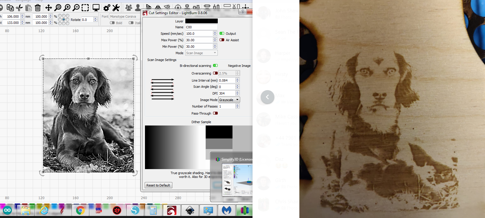
Quote from Rommel1787 on December 27, 2018, 9:16 pmIm trying to grey scale with lightburn. not really the results i was expecting. not really grey scaling. Anyone got any input?
Im trying to grey scale with lightburn. not really the results i was expecting. not really grey scaling. Anyone got any input?
Uploaded files:
Quote from Gabriel on December 31, 2018, 1:12 pmHi,
look at you min power an max power settings. There is no range for gray scaling.
use for example min power 10% an max power 30%.
Hi,
look at you min power an max power settings. There is no range for gray scaling.
use for example min power 10% an max power 30%.
Quote from Rommel1787 on January 9, 2019, 12:45 pmQuote from Gabriel on December 31, 2018, 1:12 pmHi,
look at you min power an max power settings. There is no range for gray scaling.
use for example min power 10% an max power 30%.
thank you i will try a few tests and see what results i get.
Quote from Gabriel on December 31, 2018, 1:12 pmHi,
look at you min power an max power settings. There is no range for gray scaling.
use for example min power 10% an max power 30%.
thank you i will try a few tests and see what results i get.
Quote from Rommel1787 on January 10, 2019, 7:44 amQuote from Gabriel on December 31, 2018, 1:12 pmHi,
look at you min power an max power settings. There is no range for gray scaling.
use for example min power 10% an max power 30%.
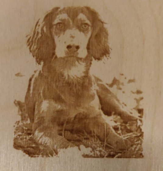
are these the kind of results i should expect? Whats your opinion?
Quote from Gabriel on December 31, 2018, 1:12 pmHi,
look at you min power an max power settings. There is no range for gray scaling.
use for example min power 10% an max power 30%.
are these the kind of results i should expect? Whats your opinion?
Uploaded files:
Quote from davegalesr on January 11, 2019, 3:37 pmMuch better. Engraving speed and $30 values also affect the quality. I typically have $30 set at 1200 and speed at 1000.
Much better. Engraving speed and $30 values also affect the quality. I typically have $30 set at 1200 and speed at 1000.
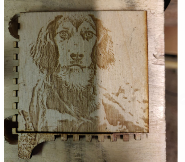
Quote from Rommel1787 on January 12, 2019, 8:35 amreduced my power and change $30 settings. Not sure what i think to the image now 😛
What image processing do you go through for engraving? I purchase photograv but not really getting the results i was hoping for.
reduced my power and change $30 settings. Not sure what i think to the image now 😛
What image processing do you go through for engraving? I purchase photograv but not really getting the results i was hoping for.
Uploaded files:
Quote from davegalesr on January 12, 2019, 9:07 amI use gimp for some of the pre-processing - it's real handy for cleaning up dirty areas in particular. Then I use inkscape for final processing and and the raster2laser extension for engraving. I use Lightburn also but not until gimp and inkscape have processed the image.
I use gimp for some of the pre-processing - it's real handy for cleaning up dirty areas in particular. Then I use inkscape for final processing and and the raster2laser extension for engraving. I use Lightburn also but not until gimp and inkscape have processed the image.
Quote from Rommel1787 on January 12, 2019, 10:25 amQuote from davegalesr on January 12, 2019, 9:07 amI use gimp for some of the pre-processing - it's real handy for cleaning up dirty areas in particular. Then I use inkscape for final processing and and the raster2laser extension for engraving. I use Lightburn also but not until gimp and inkscape have processed the image.
Id love to see more details abotu your processing if you are willing to share. here is a photo from photograv not sure if the result are realistic for the machine.
Quote from davegalesr on January 12, 2019, 9:07 amI use gimp for some of the pre-processing - it's real handy for cleaning up dirty areas in particular. Then I use inkscape for final processing and and the raster2laser extension for engraving. I use Lightburn also but not until gimp and inkscape have processed the image.
Id love to see more details abotu your processing if you are willing to share. here is a photo from photograv not sure if the result are realistic for the machine.
Uploaded files: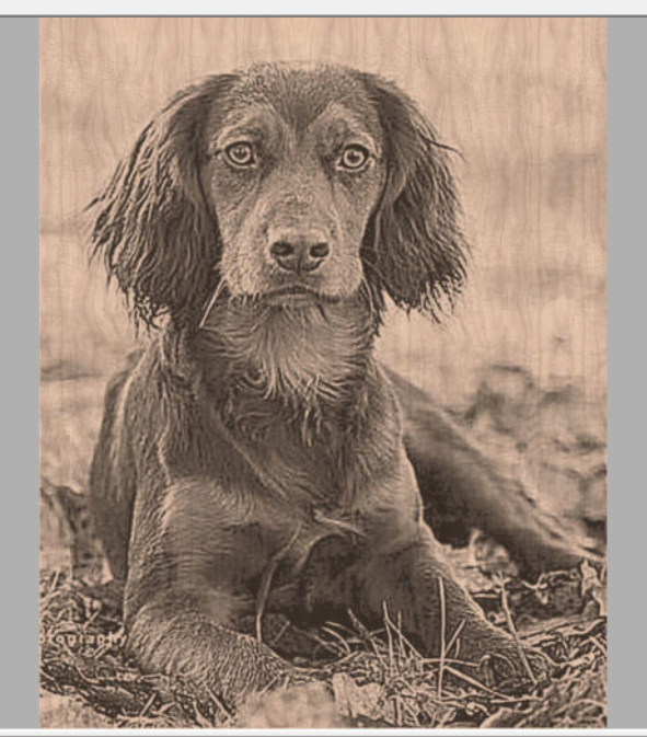
Quote from tprothma on January 13, 2019, 2:34 amdfox1787,
I've been doing a lot of engraving with a laser diode, so I have not fully characterized the ideal settings for the K40. For a properly processed image I see no reason to set min to anything other than 0%. Photograv uses dithering for which is only on/off (1bit) and not needed for Paul's controller which has full PWM control.
Here is the simplest setup:
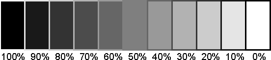
Min dot size: This is based on optics as 16 microsteps is more than enough res for our steppers. I'd start with diagonal at 0.15mm.Start with a greyscale test pattern I've attached. I had to create my own greyscale that has never been converted to jpg (only a BMP) which will add anomalies due to compression. This also eliminates variabilities with respect to your image.
Greyscale images are processed in LB as 8bit, so there are only 256 distinct values. White will give a power of 0, and black will give a power of 255. Set $30 to 255, set $31 to 0, you do this in the console window of LB, $$ to confirm they were set. In LB go to Edit->Device Settings and set S value max to 255. Now everything is basically aligned (this is not optimizing the granularity, but easiest to understand so I recommend starting with that). Then set min power to 0% and max power to probably 10%. This means a black dot would be set to 26 (10% of S max)and a white dot is zero. This 10% (relatively low) power setting is because the 40W laser is more than enough power to burn the top of the plywood. Then start sweeping speed and find the correct speed for the assigned power which gives a good greyscale. Probably start with something like 20mm/s. Yes, it's a lot faster than cutting. If it's overburning (digging into the material, run the speed faster).
My disclaimer is that I've not done this on the K40, so I don't know if 10% has an achievable speed or whether we will max out the speed and still overburn. If still over burn at the maxed out speed, then bring down the power. Hopefully it's making sense how things are linked.
Someone may be able to give you more precise combinations for our machine, but I've been working on a diode laser and these are the basic anchoring points (independent of machine):
1) Figure out the machine's Line Interval (based on optics for K40)... too big and there will be gaps between the lines, too small and there will be overlap. Setting incorrectly in either direction will look make the image lose clarity.
2) Align $30 and Smax, this ensures the Controller is interpeting the Gcode properly.
3) Fix max power at some relative low value (guessing between 10% and 20%) and set min to 0% this means whites do not get burned.
4) Sweep speed until you find the right speed based on that power. The correct combination will give you dark and light with nice range in between.
5) Start with a greyscale image and get it looking nice, then use your target image. Attached is one I created which each box is 5x1omm and the text is vector based text, then converted to a raster image directly.
6) If you suspect backlash on your machine, deselect Bi-directional. I've written special python code to take a high end image conversion software output and do unidirectional engraving. LB lacks some knobs I like for getting a good range as I'm trying to do photographic quality engravings.
Paul's controller is in fact Awesome! I just ran out of steam with C02 lasers as the limitations are not the controller. The limitation was the dynamic response of the C02 laser and went to a laser diode.
My eye for a good pre-processed image and a good engraving has improved, yours will too... Don't settle. Understanding the fundamentals has been a tiresome chore, but I'm a knowledge seeker so I roll up my sleeves and hammer away at a problem. I'm still learning... and sharing... Please share back once you've made progress.
Tim
dfox1787,
I've been doing a lot of engraving with a laser diode, so I have not fully characterized the ideal settings for the K40. For a properly processed image I see no reason to set min to anything other than 0%. Photograv uses dithering for which is only on/off (1bit) and not needed for Paul's controller which has full PWM control.
Here is the simplest setup:
Min dot size: This is based on optics as 16 microsteps is more than enough res for our steppers. I'd start with diagonal at 0.15mm.
Start with a greyscale test pattern I've attached. I had to create my own greyscale that has never been converted to jpg (only a BMP) which will add anomalies due to compression. This also eliminates variabilities with respect to your image.
Greyscale images are processed in LB as 8bit, so there are only 256 distinct values. White will give a power of 0, and black will give a power of 255. Set $30 to 255, set $31 to 0, you do this in the console window of LB, $$ to confirm they were set. In LB go to Edit->Device Settings and set S value max to 255. Now everything is basically aligned (this is not optimizing the granularity, but easiest to understand so I recommend starting with that). Then set min power to 0% and max power to probably 10%. This means a black dot would be set to 26 (10% of S max)and a white dot is zero. This 10% (relatively low) power setting is because the 40W laser is more than enough power to burn the top of the plywood. Then start sweeping speed and find the correct speed for the assigned power which gives a good greyscale. Probably start with something like 20mm/s. Yes, it's a lot faster than cutting. If it's overburning (digging into the material, run the speed faster).
My disclaimer is that I've not done this on the K40, so I don't know if 10% has an achievable speed or whether we will max out the speed and still overburn. If still over burn at the maxed out speed, then bring down the power. Hopefully it's making sense how things are linked.
Someone may be able to give you more precise combinations for our machine, but I've been working on a diode laser and these are the basic anchoring points (independent of machine):
1) Figure out the machine's Line Interval (based on optics for K40)... too big and there will be gaps between the lines, too small and there will be overlap. Setting incorrectly in either direction will look make the image lose clarity.
2) Align $30 and Smax, this ensures the Controller is interpeting the Gcode properly.
3) Fix max power at some relative low value (guessing between 10% and 20%) and set min to 0% this means whites do not get burned.
4) Sweep speed until you find the right speed based on that power. The correct combination will give you dark and light with nice range in between.
5) Start with a greyscale image and get it looking nice, then use your target image. Attached is one I created which each box is 5x1omm and the text is vector based text, then converted to a raster image directly.
6) If you suspect backlash on your machine, deselect Bi-directional. I've written special python code to take a high end image conversion software output and do unidirectional engraving. LB lacks some knobs I like for getting a good range as I'm trying to do photographic quality engravings.
Paul's controller is in fact Awesome! I just ran out of steam with C02 lasers as the limitations are not the controller. The limitation was the dynamic response of the C02 laser and went to a laser diode.
My eye for a good pre-processed image and a good engraving has improved, yours will too... Don't settle. Understanding the fundamentals has been a tiresome chore, but I'm a knowledge seeker so I roll up my sleeves and hammer away at a problem. I'm still learning... and sharing... Please share back once you've made progress.
Tim
Uploaded files:
Quote from tprothma on January 13, 2019, 3:08 pmI quickly found that the $30 and Smax are not integers so fractional values (floats) are interpreted fine. Thus set 255 for both $30 and Smax and adjust power/speed in LB. I think Paul intended $30 to be used differently, but like being able to interrogate Gcode and knowing the darkness level based on S level is aligned.
Also LB, Picengrave, and I believe a lot of commercial SW align the DPI based on line interval (scan interval). I've seen people indicate that 300dpi is a good point for K40, but that's 2x what I'm using below, and I'd suspect that they're getting a lot of blending (but it will burn in deep) and their eyes are not able to distinguish that the dots are overlapping (averaging) but it's pleasing to their eye so they believe it's best- although IMO non-scientific. A little overlap is probably ok, I suspect they're getting up to 50% overlap, again it comes down to optics spot size.
I fixed the line interval at 0.15mm and an engraving angle of -45deg. I got no spaces between lines. I see a lot of good engravings posted online that clearly have separation in some cases and I can also tell a dithered image from true greyscale.
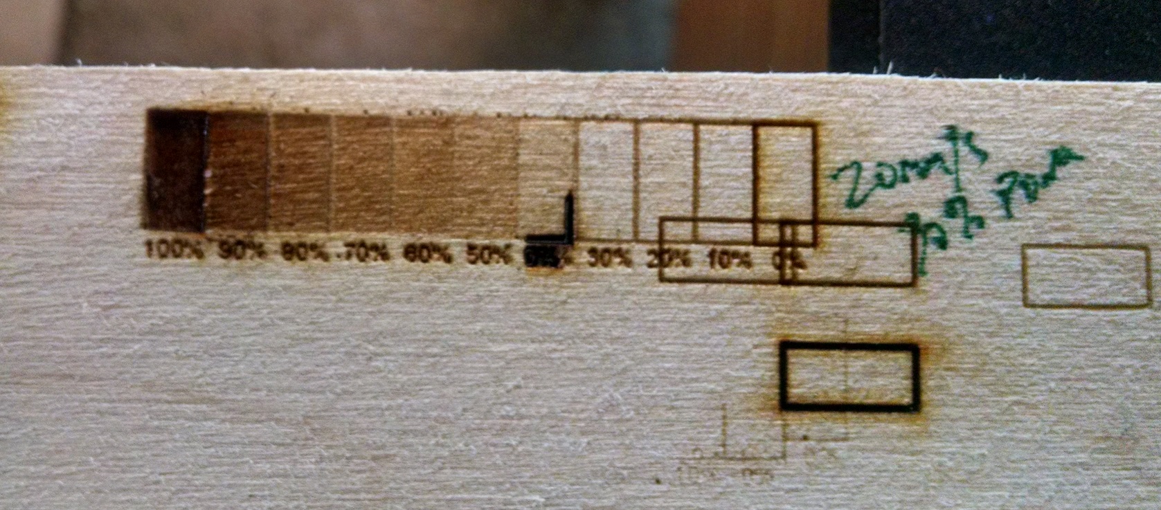
I tried 3mm Birch and found that I needed around 30%power to get any results, but felt I had to run it slow (20mm/s). I used vector (boxes) at low power (vector engraving) to figure out the target speed/power to get nice dark burn and I felt that somewhere around 3-10mA is sufficient. I found that it had to dig in a bunch to really get dark. So I considered that birch is not the best test material.
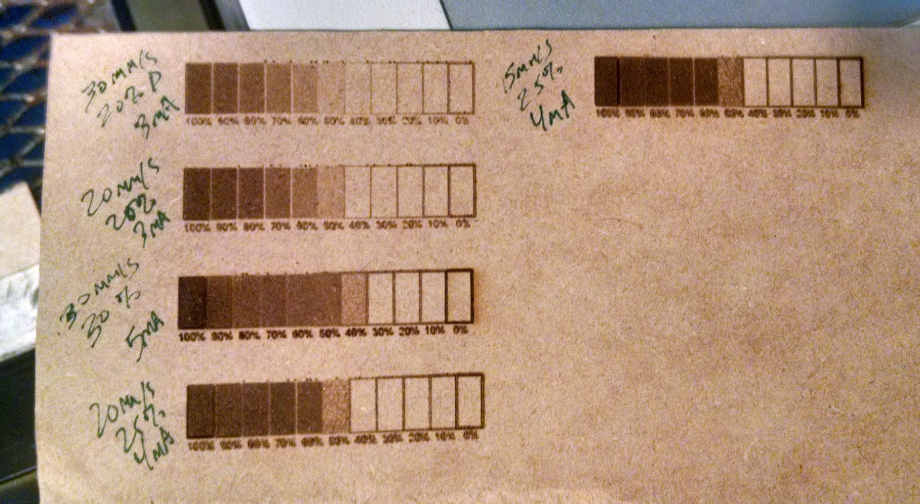
I used MDF and set a power target based on mA. I think the target for power is on the order of 3-5mA for MDF, it may need to be a little higher for birch. Attached are the results. I probably need to clean my mirrors/lens and align my machine a little so consider it a rough baseline. I only had about 1hr last night before I got too tired. I need to take the girls to get a horse trailer today and will likely have no other time this weekend. LB is able to do the sweeps of power and speed independently using layers. I considered setting up a template, which I will probably do later. I took a shortcut just to test the recipe I gave you above.
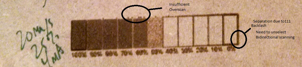
Also my overscan is a little too low (at 2mm) and I recommend unidirectional scanning because there are gaps that seem related to backlash.
I'm using $28=0 (default)
Overall I think the target powers to achieve 3-5mA for MDF and a little higher for birch (or alder which I don't have) may be correct. On the other hand I'm surprised at how slow I had to run it. Seems like 15-25mm/s is slow, I'm using 28-32mm/s on my 2.5W laser diode.
Tim
I quickly found that the $30 and Smax are not integers so fractional values (floats) are interpreted fine. Thus set 255 for both $30 and Smax and adjust power/speed in LB. I think Paul intended $30 to be used differently, but like being able to interrogate Gcode and knowing the darkness level based on S level is aligned.
Also LB, Picengrave, and I believe a lot of commercial SW align the DPI based on line interval (scan interval). I've seen people indicate that 300dpi is a good point for K40, but that's 2x what I'm using below, and I'd suspect that they're getting a lot of blending (but it will burn in deep) and their eyes are not able to distinguish that the dots are overlapping (averaging) but it's pleasing to their eye so they believe it's best- although IMO non-scientific. A little overlap is probably ok, I suspect they're getting up to 50% overlap, again it comes down to optics spot size.
I fixed the line interval at 0.15mm and an engraving angle of -45deg. I got no spaces between lines. I see a lot of good engravings posted online that clearly have separation in some cases and I can also tell a dithered image from true greyscale.
I tried 3mm Birch and found that I needed around 30%power to get any results, but felt I had to run it slow (20mm/s). I used vector (boxes) at low power (vector engraving) to figure out the target speed/power to get nice dark burn and I felt that somewhere around 3-10mA is sufficient. I found that it had to dig in a bunch to really get dark. So I considered that birch is not the best test material.
I used MDF and set a power target based on mA. I think the target for power is on the order of 3-5mA for MDF, it may need to be a little higher for birch. Attached are the results. I probably need to clean my mirrors/lens and align my machine a little so consider it a rough baseline. I only had about 1hr last night before I got too tired. I need to take the girls to get a horse trailer today and will likely have no other time this weekend. LB is able to do the sweeps of power and speed independently using layers. I considered setting up a template, which I will probably do later. I took a shortcut just to test the recipe I gave you above.
Also my overscan is a little too low (at 2mm) and I recommend unidirectional scanning because there are gaps that seem related to backlash.
I'm using $28=0 (default)
Overall I think the target powers to achieve 3-5mA for MDF and a little higher for birch (or alder which I don't have) may be correct. On the other hand I'm surprised at how slow I had to run it. Seems like 15-25mm/s is slow, I'm using 28-32mm/s on my 2.5W laser diode.
Tim
Uploaded files:
Quote from Rommel1787 on January 14, 2019, 2:05 pmthak you for the detailed explanation it has helped me try and dial my setting in more. Especially the Greyscale test.
Changing my $30 value to 255 on the k40 results in very little burning as the k40 recures $30 to be 2000 so even at max power using $30=255 gives very little power results. Saying that using the greyscale chart with the intended values does help alot. See photo.
Although looking at using 60% power on a grey scale image only shows the shade of 60% if it is present in the image so i think i just need to darken and sharpen my images may help get the results im after.
FYI i also have a diode laser which im going to dig out and try it with lightburn and see what results i get. I doubt ill get grey-scaling but definitely may see nice results with dithering.
thak you for the detailed explanation it has helped me try and dial my setting in more. Especially the Greyscale test.
Changing my $30 value to 255 on the k40 results in very little burning as the k40 recures $30 to be 2000 so even at max power using $30=255 gives very little power results. Saying that using the greyscale chart with the intended values does help alot. See photo.
Although looking at using 60% power on a grey scale image only shows the shade of 60% if it is present in the image so i think i just need to darken and sharpen my images may help get the results im after.
FYI i also have a diode laser which im going to dig out and try it with lightburn and see what results i get. I doubt ill get grey-scaling but definitely may see nice results with dithering.
Uploaded files: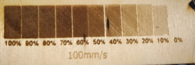
Quote from tprothma on January 14, 2019, 3:52 pmActually it looks pretty good. Some plywoods are tough to dial in. What material are you using? What is the power in mA on your analog ammeter when it's rastering on the dark (100%) areas?
For power setting, I think you're missing a key point... You have to set $30 and Smax together. Type $30="value" in console which updates the setting in grbl firmware. Set Smax in software (LB go to Edit->Device Settings and set S value max). The values are arbitrary, they just need to be in sync. If $30 is set to 1, and S max is set to 1, at 50% power Lightburn will give a S0.5 which will give tell the laser 50% pwm power. If LB gives S1.5 the controller will interpret as 100% power. You can save the Gcode in LB and then view with a text editor. "This one goes to 11" . You must watch the full video.
https://www.youtube.com/watch?v=N3L4EZwmRrA
Tone curve is your friend... You're seeing darker for a broader range, this is somewhat based on your settings, but it's common with laser engraving, so a lot of people adjust the tone curve. Generally taking the point about 2/3 of the way up the tone curve and pulling it to the upper left (slight hump) gives the best results. In addition I also use brightness, contrast, gamma, unsharp mask and a lot of other pre-processing methods as many materials do not behave in a linear way. Here's a good video (she does a really good job explaining). See also Scorchworks videos and he enables an adjustment of the tone curve.
https://www.youtube.com/watch?v=TJoPNXS1hWs
Also what are you setting for acceleration ($120 and $121)? Because if set low, you may not be getting to a full 100mm/sec. So a longer line would reach full velocity where a shorter line may not get to full velocity. Anything above 1000mm/s^2 should be enough.
You're almost there and I would definitely not pull the rip cord just yet!!! Dithering is for those without PWM.
Tim
Actually it looks pretty good. Some plywoods are tough to dial in. What material are you using? What is the power in mA on your analog ammeter when it's rastering on the dark (100%) areas?
For power setting, I think you're missing a key point... You have to set $30 and Smax together. Type $30="value" in console which updates the setting in grbl firmware. Set Smax in software (LB go to Edit->Device Settings and set S value max). The values are arbitrary, they just need to be in sync. If $30 is set to 1, and S max is set to 1, at 50% power Lightburn will give a S0.5 which will give tell the laser 50% pwm power. If LB gives S1.5 the controller will interpret as 100% power. You can save the Gcode in LB and then view with a text editor. "This one goes to 11" . You must watch the full video.
Tone curve is your friend... You're seeing darker for a broader range, this is somewhat based on your settings, but it's common with laser engraving, so a lot of people adjust the tone curve. Generally taking the point about 2/3 of the way up the tone curve and pulling it to the upper left (slight hump) gives the best results. In addition I also use brightness, contrast, gamma, unsharp mask and a lot of other pre-processing methods as many materials do not behave in a linear way. Here's a good video (she does a really good job explaining). See also Scorchworks videos and he enables an adjustment of the tone curve.
Also what are you setting for acceleration ($120 and $121)? Because if set low, you may not be getting to a full 100mm/sec. So a longer line would reach full velocity where a shorter line may not get to full velocity. Anything above 1000mm/s^2 should be enough.
You're almost there and I would definitely not pull the rip cord just yet!!! Dithering is for those without PWM.
Tim
Quote from Rommel1787 on January 14, 2019, 4:03 pmI did check and allign the $30 with LB. I used to use laserweb and the setup process is almost the same. Im using birchwood laser ply. 2ma is at 100% power.
here is a copy of my full grbl settings:
$0=10
$1=255
$2=0
$3=0
$4=0
$5=1
$6=0
$10=3
$11=0.010
$12=0.002
$13=0
$20=1
$21=0
$22=1
$23=3
$24=400.000
$25=1000.000
$26=250
$27=2.000
$28=0.000
$30=2000
$31=0
$32=1
$100=158.480
$101=159.434
$102=250.000
$110=3000.000
$111=3000.000
$112=1000.000
$120=1000.000
$121=1000.000
$122=9.147
$130=350.000
$131=250.000
$132=200.000
I did check and allign the $30 with LB. I used to use laserweb and the setup process is almost the same. Im using birchwood laser ply. 2ma is at 100% power.
here is a copy of my full grbl settings:
$0=10
$1=255
$2=0
$3=0
$4=0
$5=1
$6=0
$10=3
$11=0.010
$12=0.002
$13=0
$20=1
$21=0
$22=1
$23=3
$24=400.000
$25=1000.000
$26=250
$27=2.000
$28=0.000
$30=2000
$31=0
$32=1
$100=158.480
$101=159.434
$102=250.000
$110=3000.000
$111=3000.000
$112=1000.000
$120=1000.000
$121=1000.000
$122=9.147
$130=350.000
$131=250.000
$132=200.000