Endstops problem
Quote from Lukasz on May 25, 2019, 10:55 pmThis is my first post so - Hi everyone. I am Lukas
I have a K40 with ribbon cable and opto endstops. I connected everything according to the instructions but I have no reaction to endstops. In the lightburn console I do not have "Pn: XY" status. I tried to change the 24V power supply because I suspect groundloop. No effect. I checked if the voltage is transmitted to the endstops and is 5V. I read the Troubleshooting Guide but it also did not help me. M2 nano works correctly.
any ideas?
sorry for my English 😉
This is my first post so - Hi everyone. I am Lukas
I have a K40 with ribbon cable and opto endstops. I connected everything according to the instructions but I have no reaction to endstops. In the lightburn console I do not have "Pn: XY" status. I tried to change the 24V power supply because I suspect groundloop. No effect. I checked if the voltage is transmitted to the endstops and is 5V. I read the Troubleshooting Guide but it also did not help me. M2 nano works correctly.
any ideas?
sorry for my English 😉
Quote from Paul on May 27, 2019, 11:24 amHi, If you have opto limit switches, please ensure that they receive their 5V power supply.
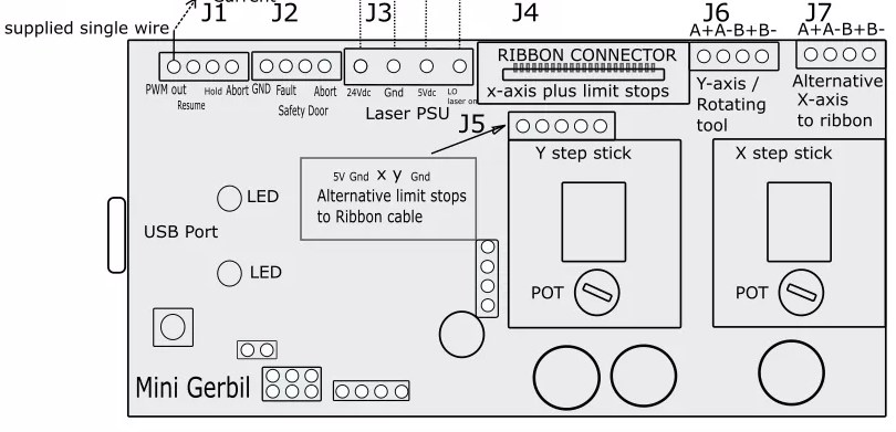
The connections on the break out pins are from left to right: GND, Y limit, X limit, GND, +5V.
Manually set the Gantry in the zero positions and measure with a multi meter (in Volt-measure setting) on the breakout pins if you get a signal. Maybe post some photo's too?
Hi, If you have opto limit switches, please ensure that they receive their 5V power supply.
The connections on the break out pins are from left to right: GND, Y limit, X limit, GND, +5V.
Manually set the Gantry in the zero positions and measure with a multi meter (in Volt-measure setting) on the breakout pins if you get a signal. Maybe post some photo's too?
Quote from Lukasz on May 29, 2019, 1:06 amI used a multimeter and I measured Y and X endstop pins. 5V voltage is on endstops. The voltage in the zero positions on the X and Y pins is 0.15V. With open endstops on the pins is 0.05V.
I used a multimeter and I measured Y and X endstop pins. 5V voltage is on endstops. The voltage in the zero positions on the X and Y pins is 0.15V. With open endstops on the pins is 0.05V.
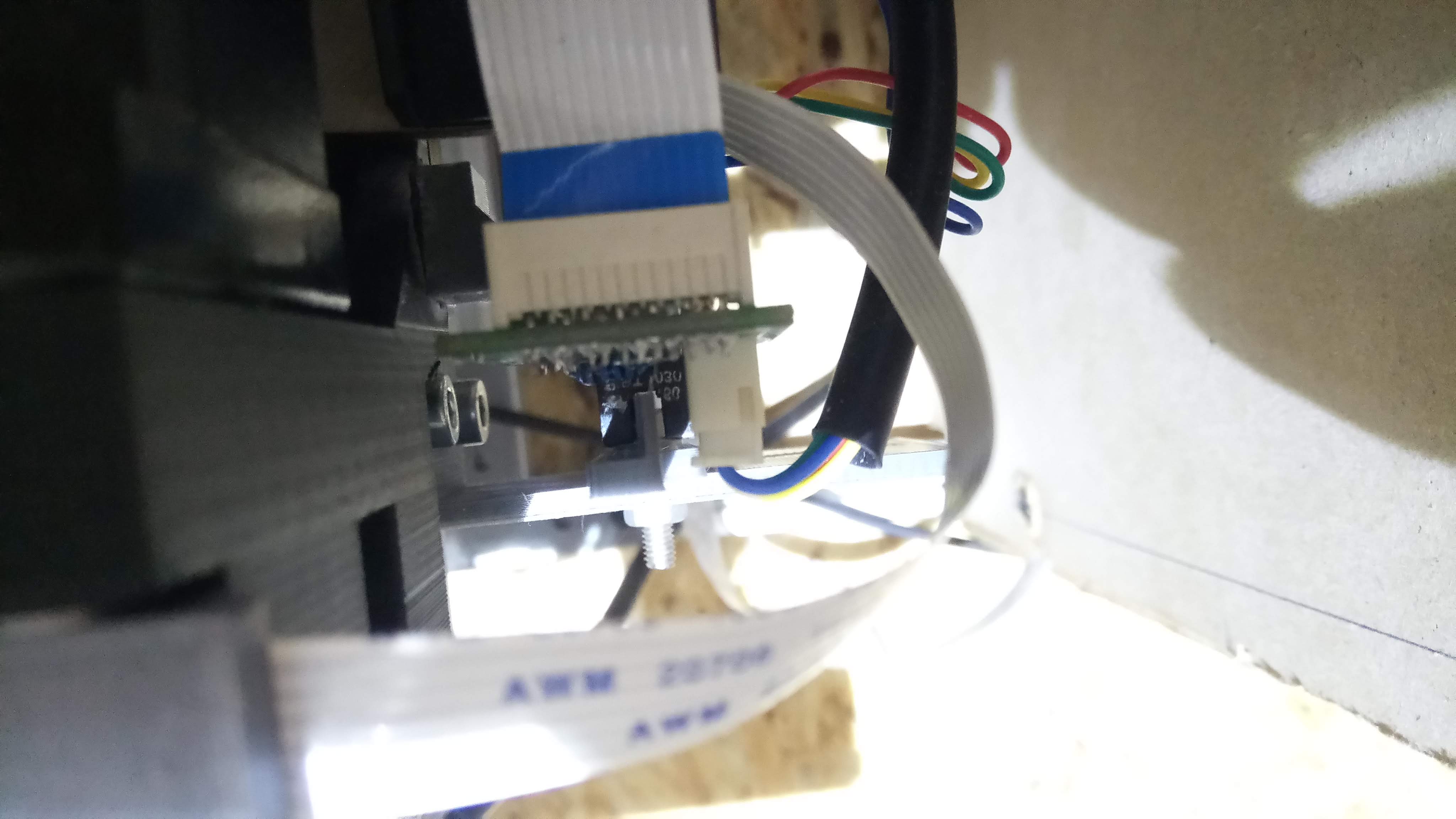
Uploaded files: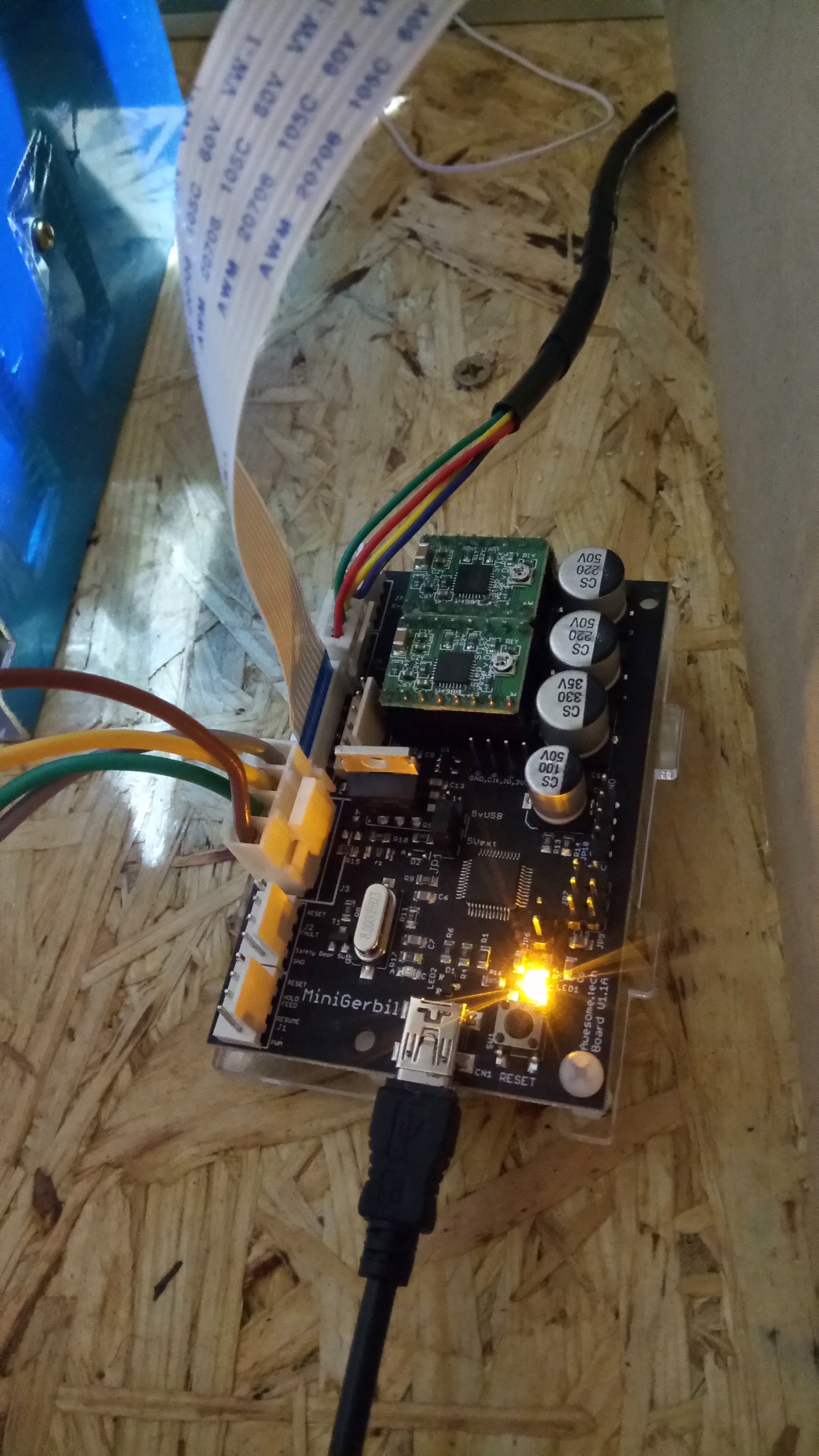
Quote from dancolwp1974 on May 29, 2019, 9:26 pmHi Lukas,
Just to confirm the measurement process - the attached diagram shows you should be measuring limit switch voltages between ground and X, and ground and Y pins on the Mini Gerbil connector J5.
For a K40, the limit switches are Normally Closed (NC), so when the gantry is away from home position, the X and Y pins should each measure around 5V relative to ground.
When the gantry is in home position, the X and Y pins measure approximately 0V.
Can you confirm the above please ?
I can see you're doing some work on your laser: just wonder if any of the following basic issues could apply:
a If your voltages are the other way around to the above description, make sure the limit switches are connected by their NC and common contacts, instead of NO and common.
b Check that you haven't mis-wired X and Y to eachother.
c With Mini Gerbil turned off, use a multimeter to check continuity (no break in your wiring) between Mini Gerbil pin X, and the end of the wire connecting to your X limit switch. Then repeat for Y. You should temporarily remove the connection to the limit switch when checking continuity so we can be 100% sure it's not backfeeding through the switch.
Once you confirm the above, we'll go from there !
Dan
Hi Lukas,
Just to confirm the measurement process - the attached diagram shows you should be measuring limit switch voltages between ground and X, and ground and Y pins on the Mini Gerbil connector J5.
For a K40, the limit switches are Normally Closed (NC), so when the gantry is away from home position, the X and Y pins should each measure around 5V relative to ground.
When the gantry is in home position, the X and Y pins measure approximately 0V.
Can you confirm the above please ?
I can see you're doing some work on your laser: just wonder if any of the following basic issues could apply:
a If your voltages are the other way around to the above description, make sure the limit switches are connected by their NC and common contacts, instead of NO and common.
b Check that you haven't mis-wired X and Y to eachother.
c With Mini Gerbil turned off, use a multimeter to check continuity (no break in your wiring) between Mini Gerbil pin X, and the end of the wire connecting to your X limit switch. Then repeat for Y. You should temporarily remove the connection to the limit switch when checking continuity so we can be 100% sure it's not backfeeding through the switch.
Once you confirm the above, we'll go from there !
Dan
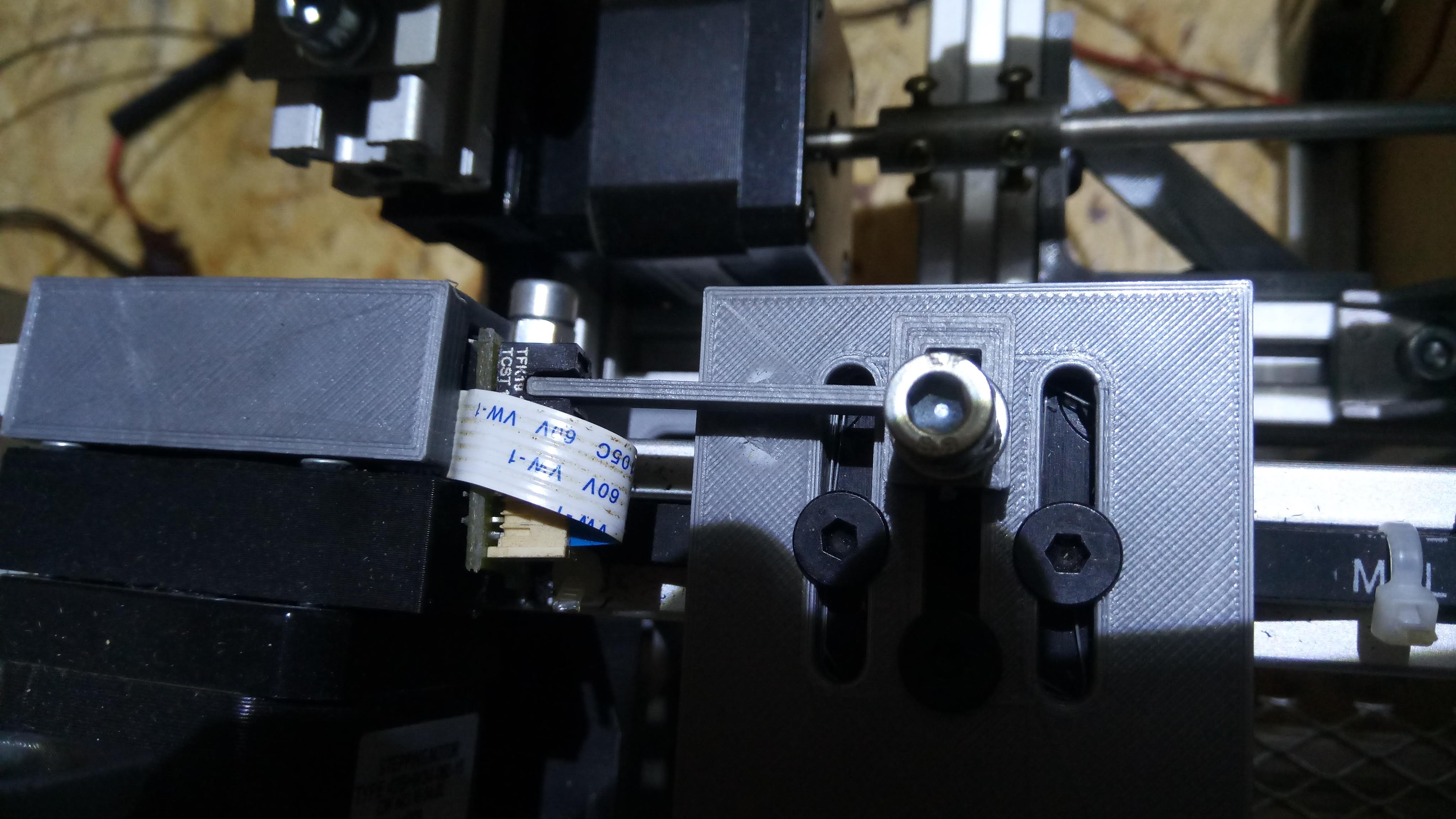
Uploaded files: