
The Personal Particle Accelerator is an advanced science demonstration and experimentation station, designed for ages 16 and up (adult supervision for ages 13 up). It is a ‘working’ model of a synchrotron particle accelerator, such as the Large Hadron Collider. Rather than accelerate sub-atomic particles to relativistic speeds, the PPA rotates a small steel ball in the range 2-10 metres per second. This user manual covers basic and advanced operating modes.
This User Manual assumes you have completed kit assembly, or have purchased a completed PPA.
Understanding the PPA
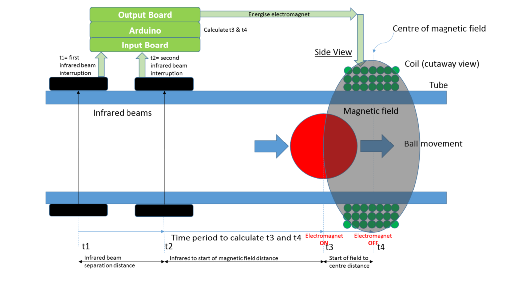
The diagram below identifies the key PPA components and their purpose.
Getting the ball rolling
Ensure you have a suitable power supply:
- Minimum: fixed power supply anywhere between 12 and 16V DC, minimum 3A
- Recommended: variable (laboratory) power supply that covers the range 12-20V DC, up to 5A
Here are the steps to get the ball rotating. It’s actually quite simple but laid out below in lots of detail to ensure you get off to a smooth start.
- Move the throttle to around 70% of the way to the top (with the 4 wire cable facing away from the user)
- Before connecting the power supply to the PPA, set its output voltage to 12V. Plug in the PPA’s power lead to the power supply with the correct polarity.
- Immediately confirm the PPA’s current is expected: it should be between 0.1A and 0.2A. If not, turn off the power supply immediately and investigate.
- Check that the EM’s are enabled. This is indicated by the endmost red LED on the bargraph, on the farside from the SMPS. If the LED is not illuminated, then toggle the Enable switch – the LED should illuminate.
- Identify a good starting position for the ball. It should be around half-way between EM’s. Avoid both the third of the main tube where the two tube ends are joined, and the third of the main tube that has an IRPS at each end.
- Tilt your baseboard until the ball rolls to the starting position. You’ll see the blue strobes flash as the ball passes through any IRPS, this is fine.
- Consider reducing the room’s brightness (eg. lights/curtains) so that the strobes will be easily visible.
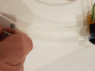
- Firmly grip your magnet as shown in Figure 2. Note that the magnet does not protrude from the fingers/hand. Slowly move your hand towards the ball, until your hand is lightly touching the tube. The fingers keep the magnet at a distance of 3-5mm from the tube.
The video below shows the technique, including using your spare hand to grip the tube – a helpful technique for beginners.
- If the ball’s initial speed is insufficient, then the strobes will flash as the ball rotates, but the ball will roll to a stop, in which case return it to the starting position and try again. Do not use the magnet to return the ball to the starting position – this may lead to placing the magnet near the electromagnet, which may result in damage or injury.
- Check the expected results:
- The ball should continuously roll around the tube and LED strobes should flash as the ball passes through each EM.
- Three LEDs in the Output Board bar graph should flash in sequence as the ball passes through the respective EM’s.
- The screen should graph the ball’s speed in metres/second. As the graph reaches the end of the screen, the screen clears and the graph begins again from the the left hand side.
- The rotating ball should produce an ongoing swish sound as it rolls around the tube. Listen carefully for any clicking sound, which could indicate that the ball is striking the edge of the tube as it travels across the tube join. If so, close any gap between the tube edges.
- The PPA should draw additional current from the power supply during operation. As the EM pulses are very short, the current displayed on your meter/power supply will vary depending on its sampling period. It can be expected that it will jump between values as EM pulses randomly align with display sampling periods.
Shutting down
To stop the ball rotating, simply toggle the EM enable switch. The last LED in the bargraph will turn off, and the ball will roll to a stop. The graph will show the speed decrease – a nice exponential decay.
To turn off the unit, simply turn off the power supply.
This page will be updated to include a description of the PPA’s screen and USB connection to PC
User Interface
The PPA’s user interface consists of the throttle unit and the screen.
The throttle consists of a linear potentiometer and two pushbuttons. The Arduino firmware can be programmed to recognise the button presses and activate customised features/display/data. A simple design would have been for the potentiometer and each pushbutton to have their own inputs to the Arduino. This wasn’t possible due to limited I/O pins on the Arduino, so the throttle’s resistor network attempts to level shift the potentiometer data in such a way that the button presses can be detected by the firmware independently of the potentiometer level. This has not been perfectly achieved with the current design!
The screen is described below.
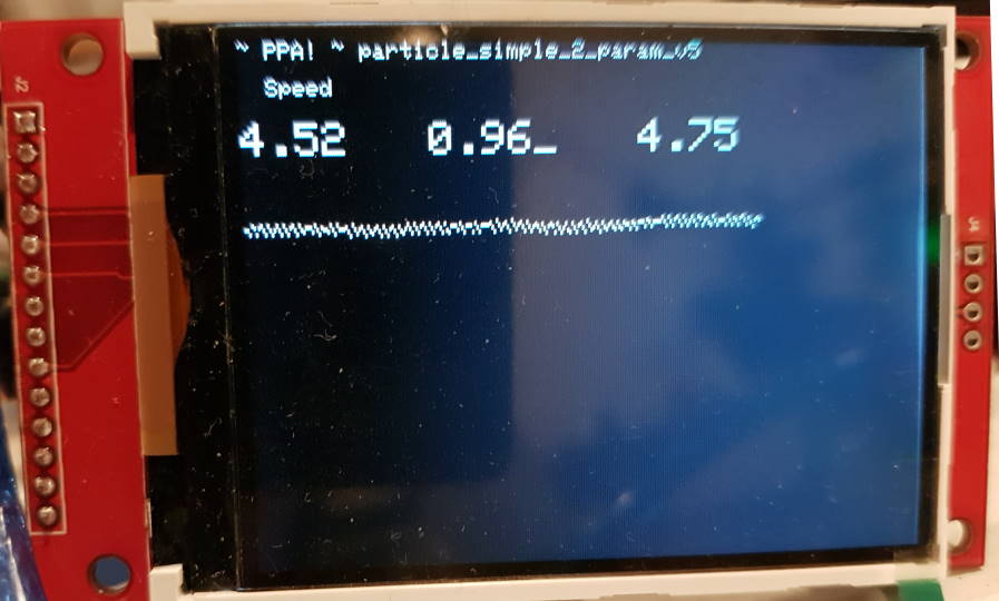
The top line of text in the screen shows the firmware filename/version – note that this needs to be manually changed each time the firmware name is changed.
The top left numeric readout is speed, in metres per second. The line graph is also showing the speed in metres per second. If you look closely, you’ll see it’s comprised of multiple dots that have some patterns. The speed data is actually obtained from the speed calculations through each IRPS. So if you see points that look out of place, for example, the dots at the bottom of the screen above, you can see that something is wrong.
The other two numeric readouts are Tuning Factor (tf) and Offset. Both are described in the Design documentation.
The underscore indicates which parameter is being edited by the throttle position, in this case, it’s the Tuning Factor. The leftmost (red) throttle button is used to move the cursor around and swap between variables. More information to follow.
There is also a mode that allows fine tuning of the throttle – press the red and green buttons simultaneously to enter. As you slide the throttle, you’ll see the raw value and the interpreted value so that you can customise the throttle interpretation values in the firmware. More info to follow.
Taking it to the next level with Processing
Processing is an easy to use programming language with easy to access graphics. The Personal Particle Accelerator includes a Processing program to demonstrate how to explore and optimise the real time system dynamics. With your PPA powered up, but not rotating, plug in the Arduino to PC USB. Then launch the Processing program, and start rotation.
The main menu shows three options (selectable with your PC’s mouse):
- Input vs Output graph
- Optimisation graph
- Kickstarter Credits
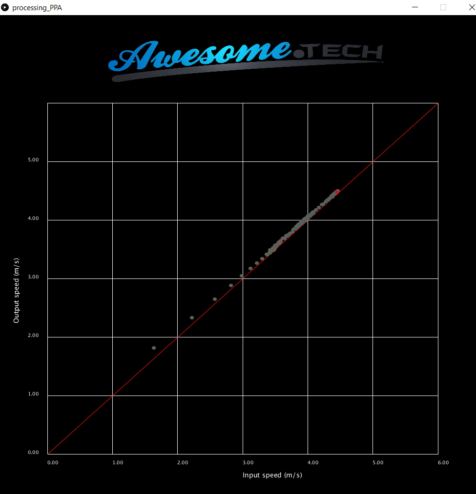
The Input vs Output graph simply plots the input and output speeds on a scatter plot, with the Tuning Factor as the plot colour. This can help the user determine the optimal Tuning Factor. Here’s an example, with the ball rocketing along at 4.5 m/s. The red point is the latest datapoint.
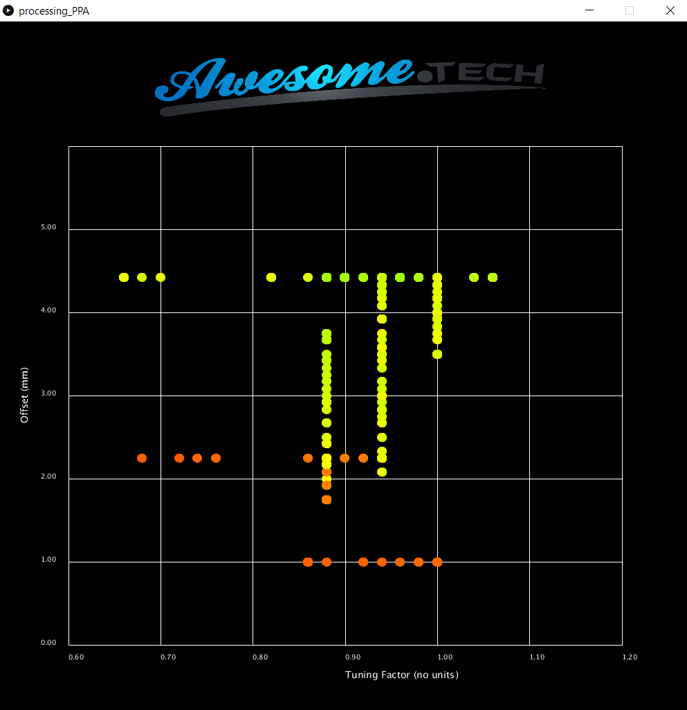
The optimisation graph below shows the result of a user navigating the Tuning Factor / Offset space, with speed mapped to colour (green is fast, in this case about 4.5m/s). It can be seen that fastest results are obtained with an offset of around 4.5mm and an offset of around 0.9.
The Kickstarter credit screen reflects some of the awesome contributors to the Kickstarter project who opted for the ‘Supporter Crew’ reward.