
60Watt Install
Quote from Wicus Botha on May 19, 2022, 9:14 pmHello everyone. I just got my MG3 and is very excited to get things going with the install, but my setup looks different than the install instructions and I need a bit of help.
Pic 1 is how my laser is set up with 3 yes 3 power supplies (holy moly)
I saw on one of the other topics a 60watt install with 2 power supplies but it didn't help me enough to get it done.
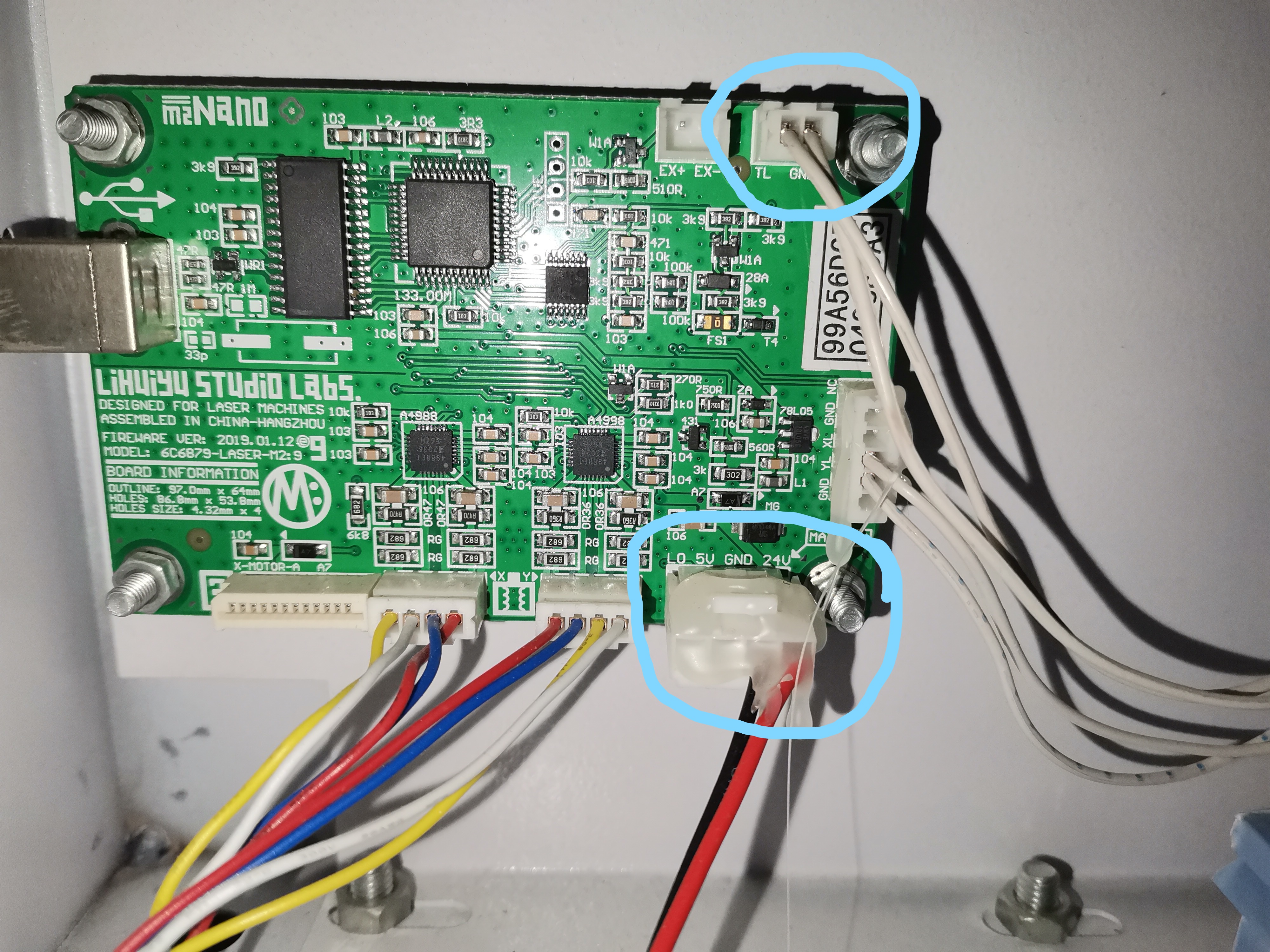
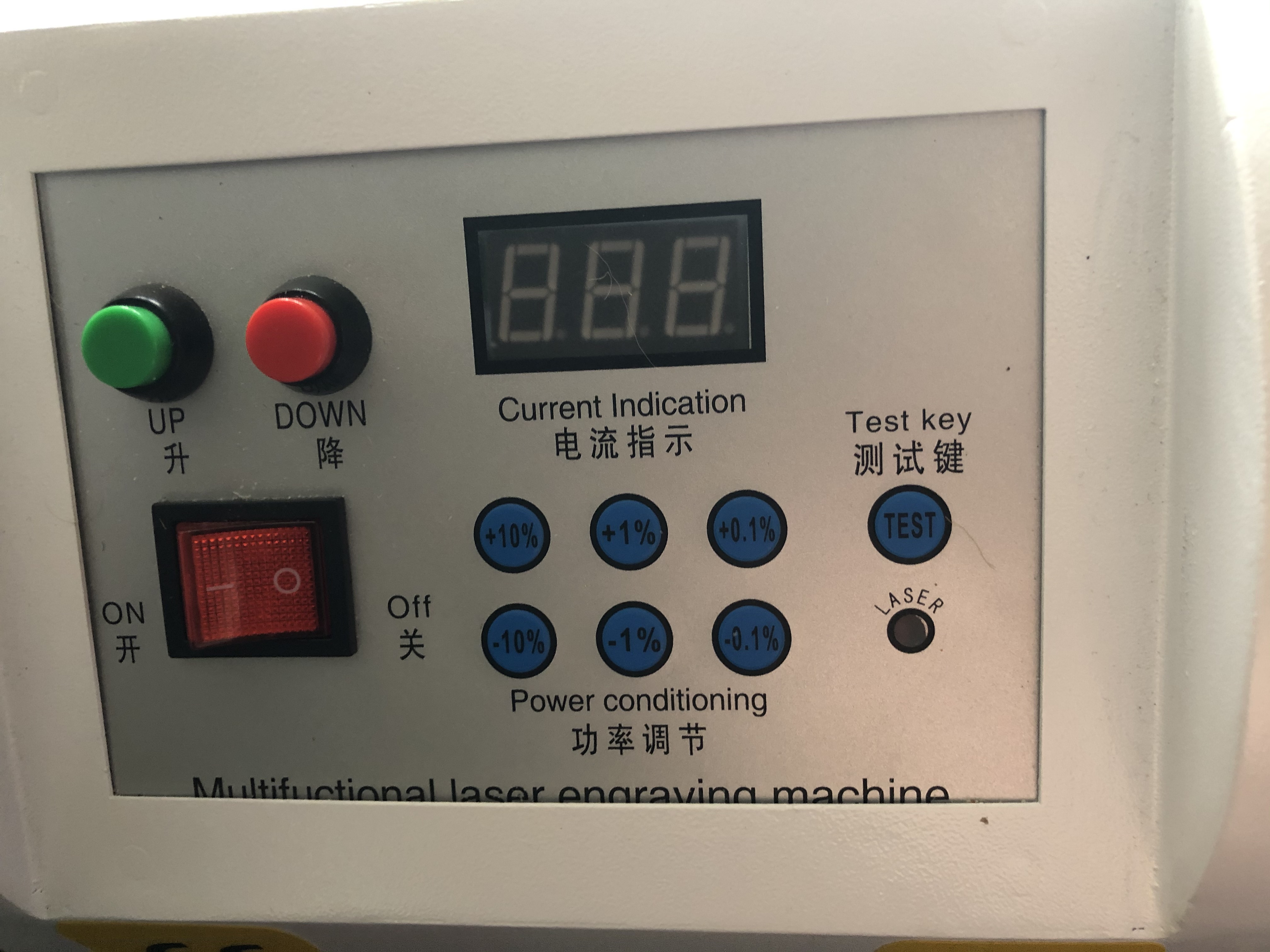
On to pic 2. Here I circled the next two questions. but first - the wire that came with the MG3 for PWM to TL on the main power supply is way to short, so if you look at the top circle of the connection there it says TL/GND and that goes directly to the TL on the main Power Supply and on the power supply side there is 2 wires in the connection the 2nd one goes to the test fire button(which will be awesome to have working still) on the panel on top of the machine. So here is Question 1: can I use this wire instead of the supplied one you gave me, and just plug that onto the PWM pin where it is supposed to go?
If you look at the bottom circle of pic 2 it is the power connector to the board. there is no 5volt wire in there, only 24volt + and -. As you can see on pic 1 I have a separate 5 volt power supply with the + & - going up to the gantry to power a red laser pointer to line up the work piece it looks like. On Pic 3 one can see a 5Volt from the main power supply that i have yet to trace, but i think it ends up on the control panel on top of the machine. Here is Question 2: from which power supply to I tap power to go to the MG3 - do I tap power from the small power supply or the main one?
Question 3: if I tap power from the main power supply do I just add a wire to the 5volt terminal or do I disconnect the wires in there and lay a new wire from there to the MG3 input.
I did install the MG3 without the 5volt wire on the plug and opened light burn and tried to home the machine but on the right hand side it said there is no 5volt power detected on the MG3 and something about the homing sensors - it was at 1 AM this morning so forgive me if I can't remember the precise wording at the moment
Thanks for all the help Dan and Paul for getting to MG3 to me so quickly
Hello everyone. I just got my MG3 and is very excited to get things going with the install, but my setup looks different than the install instructions and I need a bit of help.
Pic 1 is how my laser is set up with 3 yes 3 power supplies (holy moly)
I saw on one of the other topics a 60watt install with 2 power supplies but it didn't help me enough to get it done.
On to pic 2. Here I circled the next two questions. but first - the wire that came with the MG3 for PWM to TL on the main power supply is way to short, so if you look at the top circle of the connection there it says TL/GND and that goes directly to the TL on the main Power Supply and on the power supply side there is 2 wires in the connection the 2nd one goes to the test fire button(which will be awesome to have working still) on the panel on top of the machine. So here is Question 1: can I use this wire instead of the supplied one you gave me, and just plug that onto the PWM pin where it is supposed to go?
If you look at the bottom circle of pic 2 it is the power connector to the board. there is no 5volt wire in there, only 24volt + and -. As you can see on pic 1 I have a separate 5 volt power supply with the + & - going up to the gantry to power a red laser pointer to line up the work piece it looks like. On Pic 3 one can see a 5Volt from the main power supply that i have yet to trace, but i think it ends up on the control panel on top of the machine. Here is Question 2: from which power supply to I tap power to go to the MG3 - do I tap power from the small power supply or the main one?
Question 3: if I tap power from the main power supply do I just add a wire to the 5volt terminal or do I disconnect the wires in there and lay a new wire from there to the MG3 input.
I did install the MG3 without the 5volt wire on the plug and opened light burn and tried to home the machine but on the right hand side it said there is no 5volt power detected on the MG3 and something about the homing sensors - it was at 1 AM this morning so forgive me if I can't remember the precise wording at the moment
Thanks for all the help Dan and Paul for getting to MG3 to me so quickly
Uploaded files: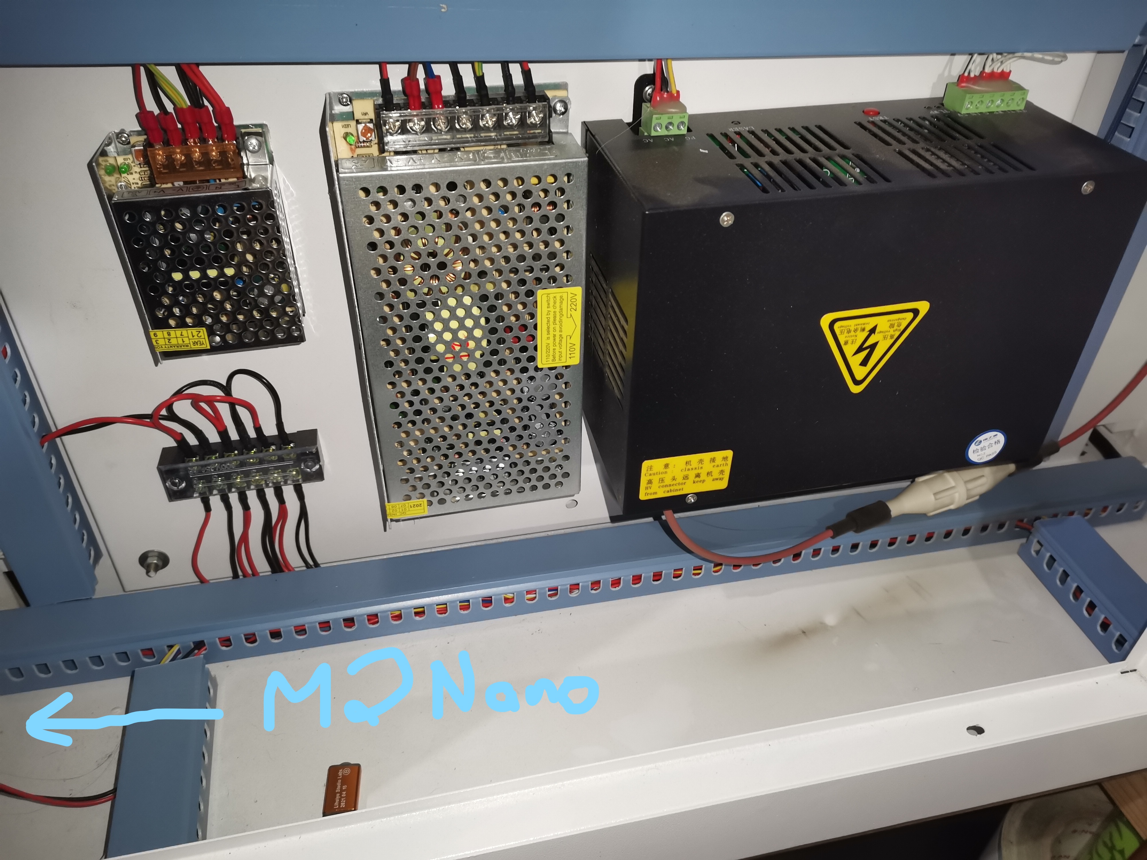
Quote from dancolwp1974 on May 19, 2022, 9:43 pmHi Wicus,
Your have an interesting laser! Don't worry, we'll get it working.
Can I simplify your questions rather than answer them directly? You've got two different topics in your post: 5V and PWM.
Let's start with 5V.
The MG3 must have 5V. It doesn't matter which power supply you get it from. It only uses around (from memory) 100mA so either should work. I take it you know that all power supplies must have the low side of their outputs (can be called V- or GND) joined?
Re the laser signals:
You may be confused. The Mini Gerbils (and any other laser controller) have two signals:
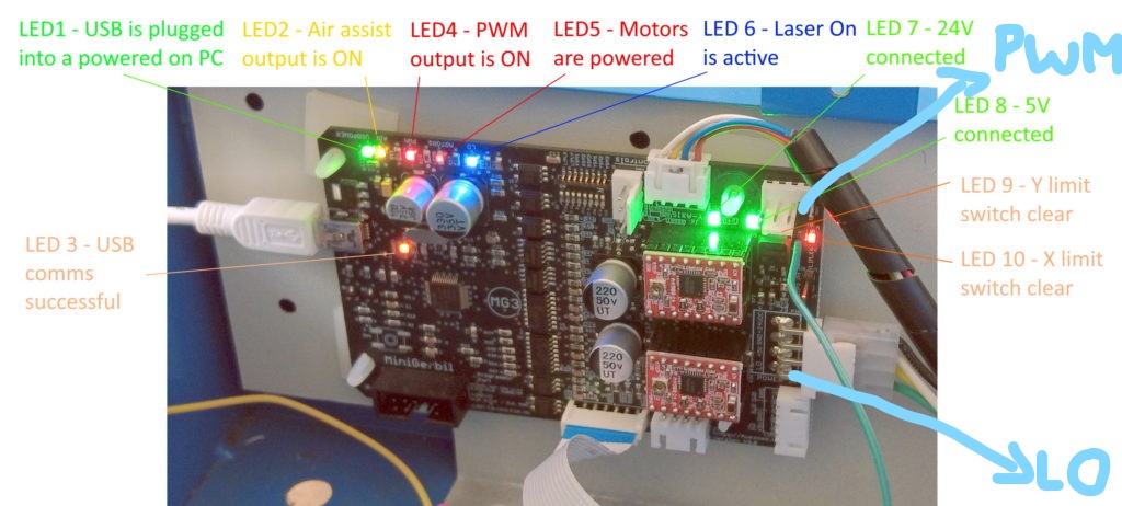
The controller PWM output is the rapidly changing signal, whose average value defines the strength of the laser. The PWM output should go to the power supplies IN input.
The controller's LO output is the enable signal that allows the laser to be activated/deactivated. It doesn't matter what the PWM is doing if the LO is inactive. LO means Laser On and its active state is when it is at 0 volts. So it should connect LO to TL because TL is the corresponding port on the power supply that is active low as well.
It's a contradiction to have the test fire button working with a digital controller in place. You want to fire the laser? Use the software. In fact, having the test fire button wired up is not good for the controller and might damage it.
Does the above help? If not, it may be easier to hand-draw a diagram showing how you propose to connect things, we can check before you do. Just be sure to label everything clearly, and don't leave any wires out.
Regards,
Dan
Hi Wicus,
Your have an interesting laser! Don't worry, we'll get it working.
Can I simplify your questions rather than answer them directly? You've got two different topics in your post: 5V and PWM.
Let's start with 5V.
The MG3 must have 5V. It doesn't matter which power supply you get it from. It only uses around (from memory) 100mA so either should work. I take it you know that all power supplies must have the low side of their outputs (can be called V- or GND) joined?
Re the laser signals:
You may be confused. The Mini Gerbils (and any other laser controller) have two signals:
The controller PWM output is the rapidly changing signal, whose average value defines the strength of the laser. The PWM output should go to the power supplies IN input.
The controller's LO output is the enable signal that allows the laser to be activated/deactivated. It doesn't matter what the PWM is doing if the LO is inactive. LO means Laser On and its active state is when it is at 0 volts. So it should connect LO to TL because TL is the corresponding port on the power supply that is active low as well.
It's a contradiction to have the test fire button working with a digital controller in place. You want to fire the laser? Use the software. In fact, having the test fire button wired up is not good for the controller and might damage it.
Does the above help? If not, it may be easier to hand-draw a diagram showing how you propose to connect things, we can check before you do. Just be sure to label everything clearly, and don't leave any wires out.
Regards,
Dan
Quote from Wicus Botha on May 19, 2022, 10:38 pmHi Dan,
wow thank you for your quick response. I must admit I am now as confused as a chameleon on a box of smarties (M&M sweets). I saw another post on the forum for a 60watt install and there it was said that the PWM wire must go to the TL on the same type of power supply as mine....
Okay so (sorry for stealing the pic off your website) if you look at Pic 4 where I marked LO must go to the power supply TL?
And where I marked PWM on pic 4 should go to power supply IN?
And then I just have to pick up a 5volt from either of the power supplies and connect that to the 5volt next to the LO ?
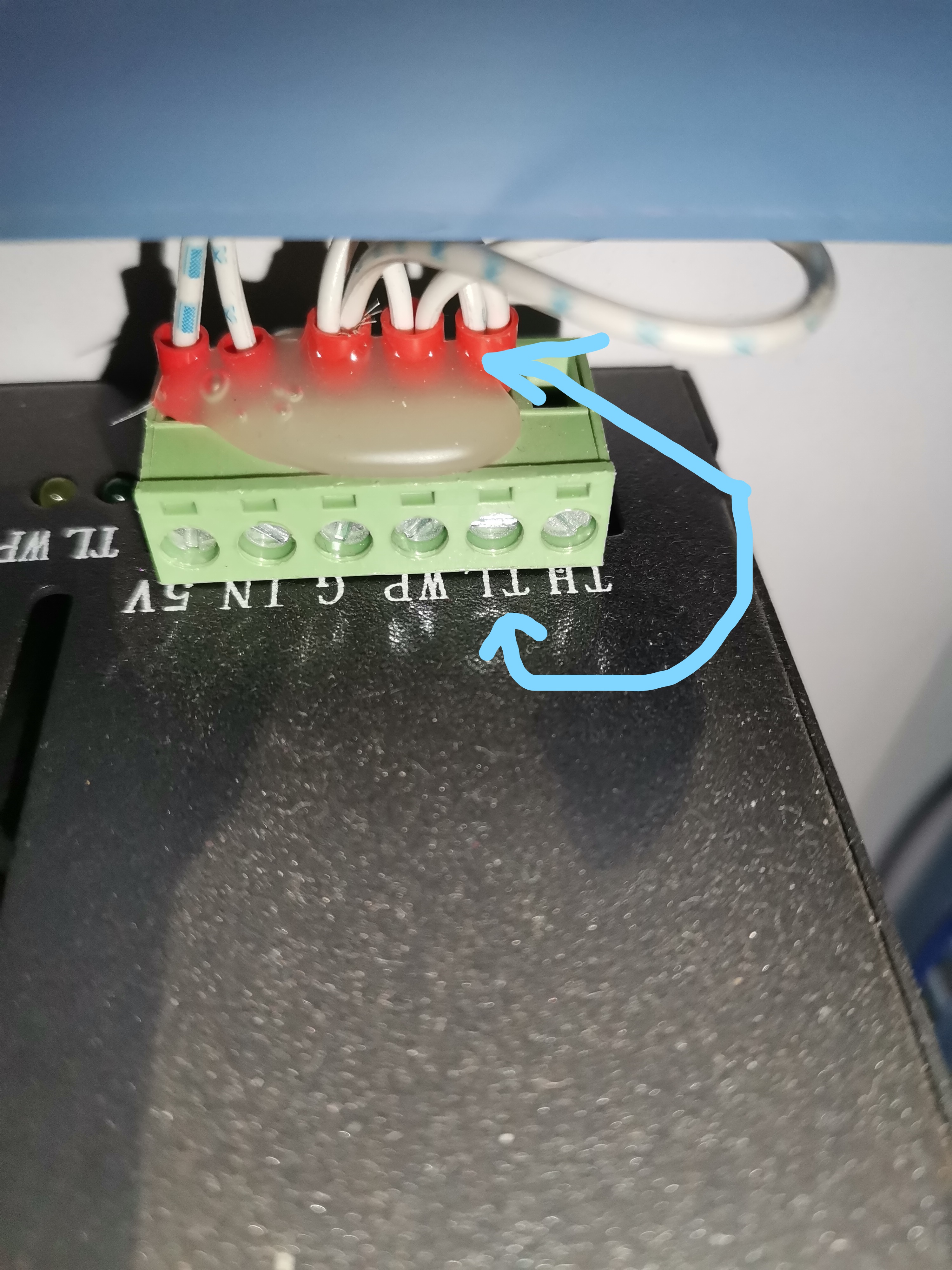
So where did the laser power supply get the signal from to switch on, if not from the m2 nano board? the control board on top (pic 5)
Hi Dan,
wow thank you for your quick response. I must admit I am now as confused as a chameleon on a box of smarties (M&M sweets). I saw another post on the forum for a 60watt install and there it was said that the PWM wire must go to the TL on the same type of power supply as mine....
Okay so (sorry for stealing the pic off your website) if you look at Pic 4 where I marked LO must go to the power supply TL?
And where I marked PWM on pic 4 should go to power supply IN?
And then I just have to pick up a 5volt from either of the power supplies and connect that to the 5volt next to the LO ?
So where did the laser power supply get the signal from to switch on, if not from the m2 nano board? the control board on top (pic 5)
Uploaded files:
Quote from Wicus Botha on May 19, 2022, 10:45 pmHi Dan,
Thinking about it now I have a switch in the front of my machine what works with a key - like a lock that switches on the laser power supply... so if I switch that off and take the key out one can still switch on the laser and jog the steppers etc. but the laser doesn't fire at all...., so the switch on the control panel brings the whole machine to life but the laser doesn't fire until you turn the key to the on position.....
Kind regards
Wicus
Hi Dan,
Thinking about it now I have a switch in the front of my machine what works with a key - like a lock that switches on the laser power supply... so if I switch that off and take the key out one can still switch on the laser and jog the steppers etc. but the laser doesn't fire at all...., so the switch on the control panel brings the whole machine to life but the laser doesn't fire until you turn the key to the on position.....
Kind regards
Wicus
Quote from Wicus Botha on May 19, 2022, 10:48 pmsorry posted the wrong pic.... here is pic 4
sorry posted the wrong pic.... here is pic 4
Uploaded files:
Quote from dancolwp1974 on May 19, 2022, 10:53 pmA chameleon in a box of smarties? ha ha ha
Maybe refer me to the other post, but the usual way to do it is PWM -> IN, and LO to TL
The LO is an output from the Mini Gerbil, so it must be wired to the TL on your photo 3. Nothing else should be connected to TL.
5V: yes, you got it. Just remember grounds must be common between the power supplies.
Yes, your labelled PWM and LO are correct.
I'd need to see a diagram of your overall wiring to understand what has to be turned on to allow the 24V to get to the controller. Bottom line is if you feed 5V and 24V directly from your power supplies, then your controller will be powered up.
Regards,
Dan
A chameleon in a box of smarties? ha ha ha
Maybe refer me to the other post, but the usual way to do it is PWM -> IN, and LO to TL
The LO is an output from the Mini Gerbil, so it must be wired to the TL on your photo 3. Nothing else should be connected to TL.
5V: yes, you got it. Just remember grounds must be common between the power supplies.
Yes, your labelled PWM and LO are correct.
I'd need to see a diagram of your overall wiring to understand what has to be turned on to allow the 24V to get to the controller. Bottom line is if you feed 5V and 24V directly from your power supplies, then your controller will be powered up.
Regards,
Dan
Quote from Wicus Botha on May 19, 2022, 11:00 pmHi Dan,
Thank you I will go fight that fight when I get home tonight and see if I can get the laser going it needs to work tonight....
Have a well deserved rest on your end of the world I know its pretty late there now its only 3 Pm here
Kind regards
Hi Dan,
Thank you I will go fight that fight when I get home tonight and see if I can get the laser going it needs to work tonight....
Have a well deserved rest on your end of the world I know its pretty late there now its only 3 Pm here
Kind regards
Quote from Wicus Botha on May 20, 2022, 6:33 amHi me again.....
Okay LO from controller to TL on power supply
PWM from controller to IN
5 volt from power supply to Controller
Switch on machine.... aaaaand it homes correctly yay!!
now a test piece cut a square... aaaaaand awwwwww the laser doesn't fire
the panel on top still has power but nothing works from there and the laser doesn't fire not even a bit of a plasma stream is visible, the light TL light on the power supply doesn't go on.... so no cigar....
I don't want to put back the Nano now....
Hi me again.....
Okay LO from controller to TL on power supply
PWM from controller to IN
5 volt from power supply to Controller
Switch on machine.... aaaaand it homes correctly yay!!
now a test piece cut a square... aaaaaand awwwwww the laser doesn't fire
the panel on top still has power but nothing works from there and the laser doesn't fire not even a bit of a plasma stream is visible, the light TL light on the power supply doesn't go on.... so no cigar....
I don't want to put back the Nano now....
Quote from Paul on May 20, 2022, 8:31 amHi Wicus, the WP input on the Laser Power supply should be grounded (probably via the safety key) in order for the laser to fire. Check whether it is connected or wire it directly to the GND screw terminal next to it. This will allow you to test it directly and if it works that you can rewire it to the safety key on the front panel.
Hi Wicus, the WP input on the Laser Power supply should be grounded (probably via the safety key) in order for the laser to fire. Check whether it is connected or wire it directly to the GND screw terminal next to it. This will allow you to test it directly and if it works that you can rewire it to the safety key on the front panel.
Quote from Wicus Botha on May 20, 2022, 8:49 amHi Paul
thanks got the laser to fire with test button on supply but I think it was more of a problem with the $ settings, but now something else is up, I went and set all the defaults of the $ settings like on your website... got the laser to fire that way but now the machine does not home....ugh... i get a alarm 9 on light burn
ALARM:9
Homing fail. Could not find limit switch within search distance. Defined as 1.5 * max_travel on search and 5 * pulloff on locate phases.
Homing did work before I fiddled with it..... I can kick myself
Hi Paul
thanks got the laser to fire with test button on supply but I think it was more of a problem with the $ settings, but now something else is up, I went and set all the defaults of the $ settings like on your website... got the laser to fire that way but now the machine does not home....ugh... i get a alarm 9 on light burn
ALARM:9
Homing fail. Could not find limit switch within search distance. Defined as 1.5 * max_travel on search and 5 * pulloff on locate phases.
Homing did work before I fiddled with it..... I can kick myself
Quote from Wicus Botha on May 20, 2022, 8:50 amjust to let you know its optic limit switches
just to let you know its optic limit switches
Quote from Paul on May 20, 2022, 9:04 amThe pull off distance of the limit switches can be set via $27. Normally set to 4mm but you can try a few e.g. 3.5, 3 and 2.5 and see if that helps.
Un-power the machine and push the gantry to zero/home position. Power the machine and see whether the leds for the limit switches on the board do turn off.
The pull off distance of the limit switches can be set via $27. Normally set to 4mm but you can try a few e.g. 3.5, 3 and 2.5 and see if that helps.
Un-power the machine and push the gantry to zero/home position. Power the machine and see whether the leds for the limit switches on the board do turn off.
Quote from Wicus Botha on May 20, 2022, 4:03 pmMorning Paul,
the leds on the limit switches does not turn off they just dim more and when I pull away the gantry they become brighter again... I'm pretty sure they were always off with the gantry away from the home position and only lit up when the gantry was in home position(with the M2 Nano)..... it was stupid of me not to copy and paste the $ settings before I started changing them. At least now if I press the test button on the laser power supply the laser does fire.
I did play with the $27 values from 1 to 10 and everything in between sometimes the error 9 becomes error 8 - still no homing
Morning Paul,
the leds on the limit switches does not turn off they just dim more and when I pull away the gantry they become brighter again... I'm pretty sure they were always off with the gantry away from the home position and only lit up when the gantry was in home position(with the M2 Nano)..... it was stupid of me not to copy and paste the $ settings before I started changing them. At least now if I press the test button on the laser power supply the laser does fire.
I did play with the $27 values from 1 to 10 and everything in between sometimes the error 9 becomes error 8 - still no homing
Quote from Paul on May 20, 2022, 6:47 pmHi Wicus, I suspect the logic levels of the limit switches are not good enough to pull the limits.
Would you be able to check the 5V level on the big connector? Alternatively we can replace the limit switches with improved opto limit switches (1k Ohm resistor on the stock limit pcbs are too high. They should be between 150-390Ohm). Or if you are handy you could replace the resistors on the limit switches.
If it was the pull off switch setting you should have found a good value between 2-4mm so I guess the limit switches are the culprit. Let me know if I can help you with the limit switches.
Hi Wicus, I suspect the logic levels of the limit switches are not good enough to pull the limits.
Would you be able to check the 5V level on the big connector? Alternatively we can replace the limit switches with improved opto limit switches (1k Ohm resistor on the stock limit pcbs are too high. They should be between 150-390Ohm). Or if you are handy you could replace the resistors on the limit switches.
If it was the pull off switch setting you should have found a good value between 2-4mm so I guess the limit switches are the culprit. Let me know if I can help you with the limit switches.
Quote from dancolwp1974 on May 20, 2022, 7:29 pmHi Wicus,
in addition to what Paul's response, the symptom could also reflect the power supply output grounds are not joined. Could you please reply with a photo showing where the power supply grounds join, so we are all 100% sure of this? Please also check the ground connection to the metal frame is good, and include a photo of this.
Thanks
Dan
Hi Wicus,
in addition to what Paul's response, the symptom could also reflect the power supply output grounds are not joined. Could you please reply with a photo showing where the power supply grounds join, so we are all 100% sure of this? Please also check the ground connection to the metal frame is good, and include a photo of this.
Thanks
Dan