
Debugging the Controller set up
This guide is to provide you with some assistance on how to debug a non working set up.
Debugging consist of 5 easy steps in logical sequence:
- Comms
- Motion
- Limit switches
- Laser power
Communication test
Start with the comms testing to see whether the board can communicate with your computer. Use a gcode sender to see the status message of the controller. For example I use CNCjs for easy usage and it can be found here https://github.com/cncjs/cncjs/releases
See if you can connect via the com port, baudrate 115200 and grbl protocol
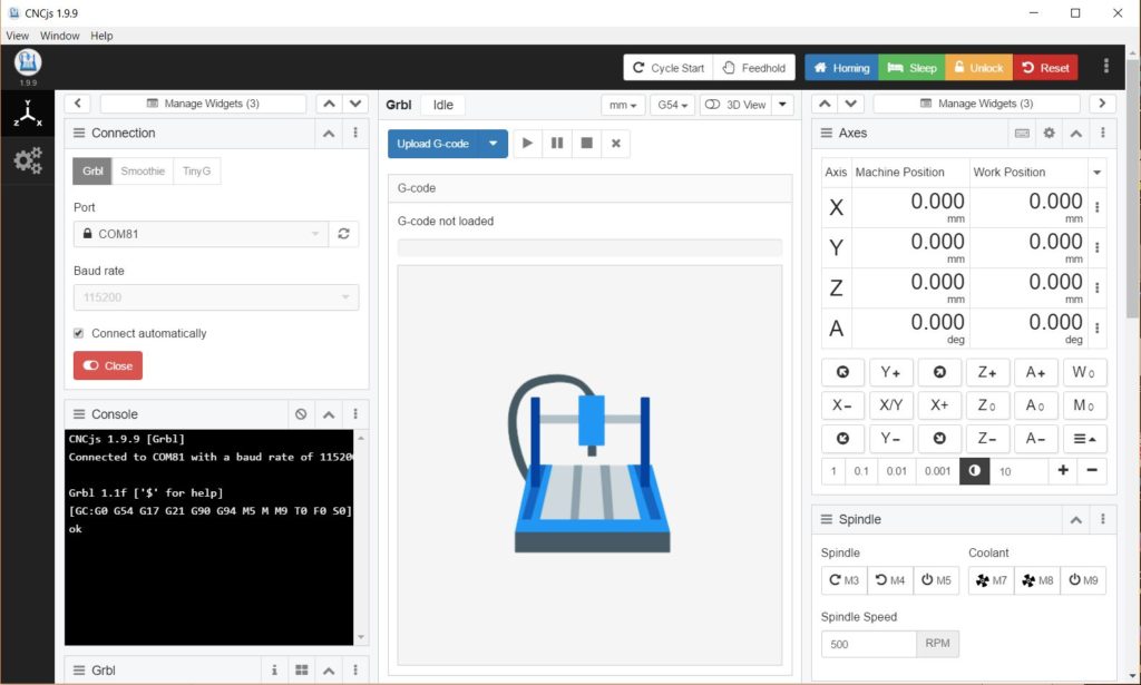
If not check that you have a comms cable and not just a charger usb cable. Check if the controller is powered (LED burns bright) and check if the FTDI driver is loaded (MS device manager). Alternatively try another PC WIN10 or OSX.
Motion test
If comms works then test motion. Makes sure the gantry is in the middle of the working space so it does not run into the sides. Issue X and Y jogging commands by clicking on the X-, X+ and Y- ,Y+ buttons. Does it move? Check the connections especially the 24V connection in the big plug on the K40 shield. Use a multi meter to check.
Next thing is to test the correct direction. Issue a $H command to see if the machine homes and hold you hand on the K40 on/off switch to prevent the machine crashing when it travels into the opposite direction (zero is left upper corner).
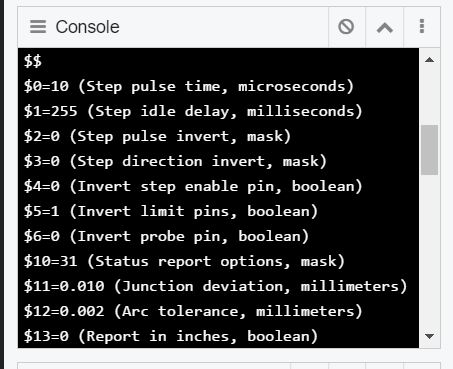
If Y is travelling opposite then you can turn the Y axis connector around or issue a $3=2 command in the Console (click in the black field to enter it). Issue $$ to read out the current config.
Next to test are the limit switches if the machine travels to zero during a homing but it crashes. To test the limit switches, you set the gantry in the middle of the space and issue a ? <enter> in the console. I should read out something like:
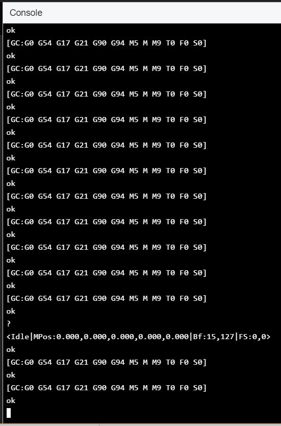
If one of the limit switches is engaged , e.g. X axis you should see this: PN:X
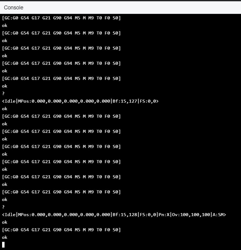
Limit switches should be NC (normally Closed). If yours are NO then you can invert the limit pins via $5 (1=X axis, 2=Y axis, 3=both axis). Check by moving the laser head gantry in the zero positions, Y and then Y and both and inspect the status by issuing a ?<enter> command.
Some K40s do have electronic limit switches which require 5V. So check with a multi meter and inspect the limit switch.
Laser test
Next step is to check the laser function. The easy way to test is to put the controller into CNC mode via $32=0, so you can test the laser pwm without the x and y axis motion. You can issue an M3, M4 or M5 cammand via the CNCjs interface. Set the controller in CNC mode via $32=0<enter> this allows you to fire the laser while stationary. You can switch it back to laser mode via $32=1. By the way, this is also a good method of aligning the laser beam since laser mode does not allow the laser to fire when both motor axis are idle.The controller PWM output must be connected to the Laser power supply unit via the IN terminal.
Connections Laser and Water protect LP and WP must be grounded and LO (Laser On=grounded) is controlled by M3/4 and M5.
Click on M3 or 4 to turn on and M5 to turn off in CNCjs and use the RPM to change the S parameter. S100 stands for 1 mA so S1000=10mA. Start small, like RPM 100 (S100=1mA).
Check with a multi meter whether LO goes to zero if M3 or M4 are issued. If so, then check WP and LP (fire switch on the front panel).
Hope this little debugging guide helps you. Good luck or else contact us or post a question on the K40 forum if it’s not covered there.