
** debugging pages will be added by request according to customer needs. Email support@awesome.tech to make a request **
Nothing happening when you spin the ball around your PPA? Ok, let’s debug.
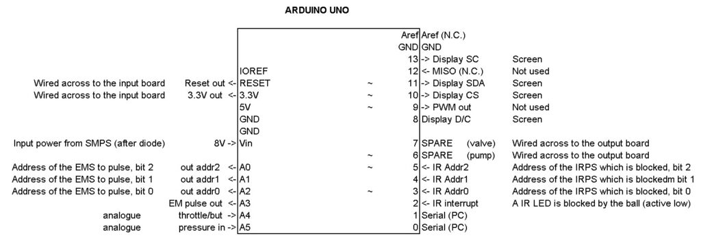
The Input board sends the signals from the IRPS to the Arduino, summarised as an IR interrupt signal and Address bus.
The IR interrupt signal flows to Arduino Pin 2 (accessible via the black header on the input board), and operates as active low. This means that when a ball is interrupting a beam, Pin 2 should have a low voltage (ie. under 1V). Otherwise, Pin 2 should read over 4.5 V.
If you make your own LED indicator (consisting of a regular red LED and a 330 ohm resistor connected to ground) and connect the LED anode to Pin 2, the LED should usually be ON (ie. the sensor is not triggered). Flashing OFF corresponds to the ball triggering the IRPS.
If Pin 2 works correctly (flashes ON/OFF/ON as the ball rolls through an IRPS), the problem must be downstream in the Arduino.
Otherwise if Pin 2 is stuck LOW (ie. LED off) that means that one of the IRPS is ‘blocked’ all the time, so we need to read out the address bus to get the address of the faulty IRPS.
Or if Pin 2 is stuck HIGH (ie. the LED is ON), then let’s see where a genuine IRPS beam interruption goes wrong by tracing the signal from the IRPS all the way through the input circuit board:
Step 1 Roll off one of the IRPS’ o-rings, and remove the top black 3d printed cover.
Step 2 See if the IR LED is working – grab your smart phone and check the LED (the devices near the 4 pin connector). To see how: https://www.youtube.com/watch?v=vsSZ3IMUQYE . If you see nothing, review the IRPS wiring info as you may have inserted LEDs back to front. Also check that you have the 4 pin cables from Input board to IRPS the right way around – match the + indicators on the Input Board and IRPS boards. Fix any other IRPS with the same issue and retest PPA operation.
Step 3 If you saw a small violet light from the LED on your smartphone screen, set your multimeter to measure voltage. Connect your negative probe to ground and your positive probe to either of the points circled in red in the picture below:
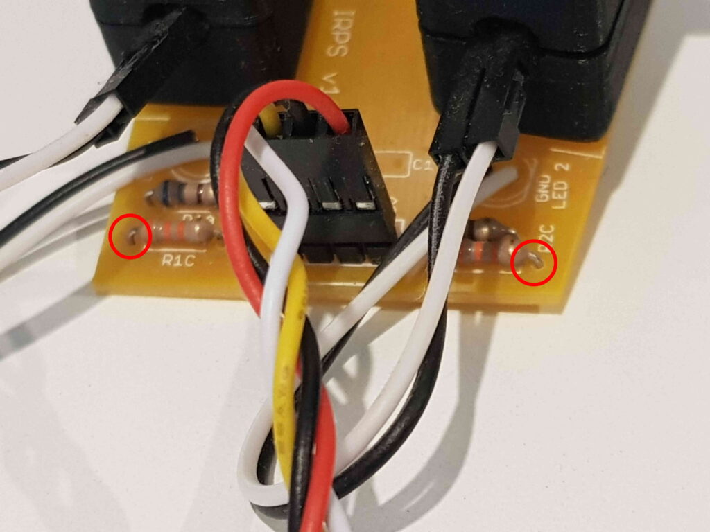
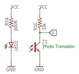
When IR light is being sent by the IR LED and correctly received by the opposite IR transistor, the voltage on the indicated point should be LOW. Try manually blocking one of the LEDs (with a pencil if you have removed the IRPS completely, or just by moving the LED away if you have taken off the top shell). If you don’t see a transition from LOW to HIGH during blocking, there’s something wrong with the phototransistor – double check the phototransistor orientation and the IRPS instructions. If you see a voltage transition from LOW to HIGH during blocking, then the IR phototransistor is working ok and we proceed to investigating the Input board in step 4.
Step 4 Let’s trace the correctly functioning phototransistor signal through the first half of the Input Board. Here’s the circuit:
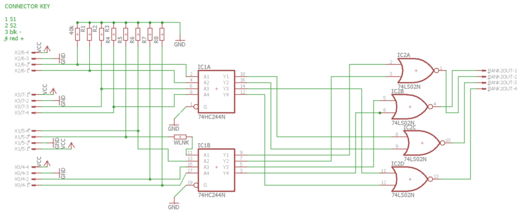
Find the IRPS you’re checking on the left, and trace to the relevant left hand side input pins on the Schmitt Trigger 74HC244. Carefully probe the relevant input and check it’s still functioning as you block/unblock the IRPS beam. Then carefully check the relevant output pin follows the signal as well. If the signal is not getting through the 74HC244, check you’ve assembled the Input board correctly and don’t have that integrated circuit chip back to front.
If the 74HC244 output is working ok, follow the diagram above and check the input of the 74LS02 follows the signal. Then check the output pin of the 74LS02 follows the signal (note that it’s an inverting OR gate). If the signal’s not getting through ok, check you’ve assembled the Input board correctly and don’t have that integrated circuit chip back to front. If it’s ok, proceed to Step 5.
Step 5 Let’s trace the correctly functioning signal through the second half of the Input Board. Here’s the circuit:
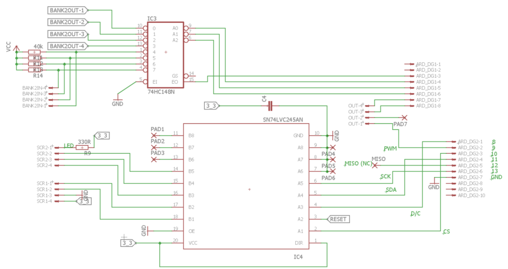
Continue tracing the signal from the OR gate through to the 74HC148. The relevant 74HC148 input should change as you block/unblock the IR beam. And that just leaves the output of the 74HC148. If it doesn’t follow the signal correctly, check you’ve assembled the Input board correctly and don’t have that integrated circuit chip back to front. The function table in the datasheet can be read to assist debugging: http://www.ti.com/lit/ds/symlink/sn74hc148.pdf