
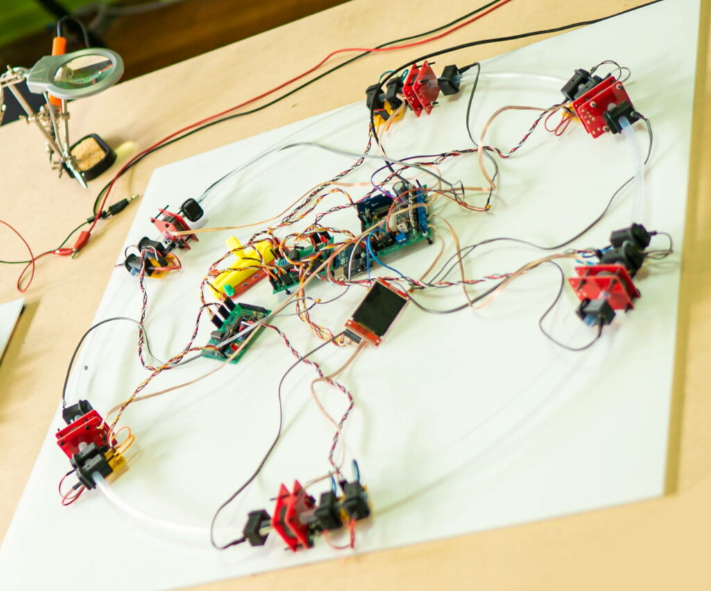
Follow the Standard PPA assembly, with the Arduino positioned near the centre.
When threading the EMS units over the tube, ensure the two with the shorter EMS wires are adjacent to eachother. This will make positioning of the Output board easier.
The Super PPA uses 6 EMS at least 6 IRPS. A 7th IRPS can be used for fine tuning the parameters, because if you’ve got this far in the instructions, you’re already a ‘turn the amplifier up to 11’ kind of person. So you can plug in 7 or 8 IRPS and don’t worry, they’ll be configured as needed in the software. Further below I outline how to terminate unused IRPS inputs.
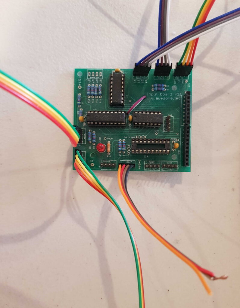
Second Input Board
The Secondary Input Board connects to the first input board with the following connections:
- The Primary Input Board (the one plugged into the Arduino) supplies power to the secondary Input Board: connect a 4 wire jumper from the Primary PWR-OUT to the Secondary PWR-IN.
- The Primary Input Board needs to receive the IRPS pulses and address from the Secondary Input Board. Connect a 4 wire jumper from the Primary Input Board’s BANK2IN to the Secondary Input Board’s BANK2OUT.
- Connect IRPS sensors numbers 4,5 and 6 to the Secondary Input Board. The 4 pin sockets are labelled 1/5, where ‘1’ is relevant for the Primary Input Board and ‘5’ is relevant for the Secondary Input Board.
- For any unused IRPS Input Board positions, create a dummy termination. The termination is simply tying the input low (non-trigger) so the Input Board doesn’t detect it as an IRPS unit that is triggering. The dummy termination consists of connecting three of the four IRPS wires together. The only wire that isn’t connected is the positive 5 volts, labelled ‘+’.
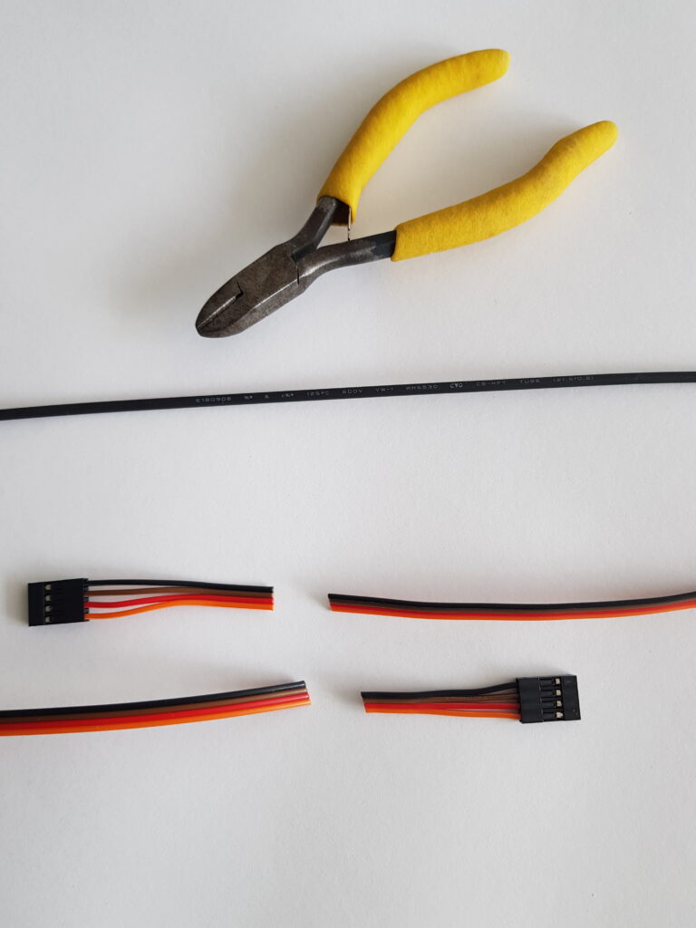
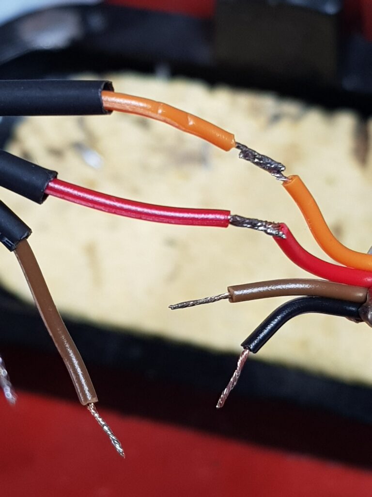
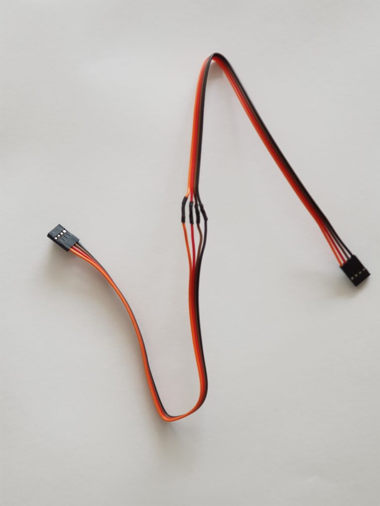
Due to the large size of the Super PPA, you can extend as many of the 4 wire cables as are needed to allow the input boards to reach the IRPS. The cables are achieved by splicing two 4 wire cables together:
It’s easier to lay the wires where the wire lengths allow, and then change the firmware to map the relationship between IRPS and EMS. Follow the instructions in Super PPA Arduino to achieve this.