
Required Tools / consumables
- Needle nosed pliers
- Engineering (clutch) pencil
- Drill and 3mm drill bit
- User supplied base board (see requirements below)
- Your 12V DC supply cable
Checklist
If you’ve completed the modules below, you’re ready to proceed to the final assembly:
- 3D printing (if applicable)
- IRPS
- Input Board
- Output Board
- Electromagnet (EM)
- Throttle
- Arduino
Base procurement
Procure a plywood or acrylic baseboard to mount the PPA to. Recommended dimensions for a standard size PPA are 40cm x 40cm, with a height of around 3mm.
Assembling the circuit boards
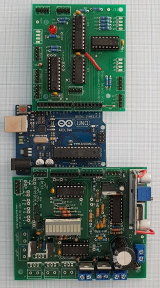
Carefully plug the Input Board’s underside pins into the Arduino as shown in Figure 1. Check to see that all pins have slid into their sockets.
Carefully plug the Output Board’s underside pins into the Arduino as shown in Figure 1. Check to see that all pins have slid into their sockets.
Position your base board onto a large flat work surface.
Take the long main tube and remove the joining connector (don’t discard it). Thread the tube through each of the EMS (electromagnet) assemblies, taking extreme care not to kink the tube. Each of the EM assemblies should have the yoke and connector rod pointing in the same direction (clockwise or anti-clockwise). The ball will travel from the side of the yoke to the electromagnet, so consider whether you want a clockwise or anti-clockwise rotation before starting. The EM’s are oriented such that their wires are on the inside of the circle.
Insert one of the steel balls from the Nuts and Bolts bag in the tube. The standard ball size is 6.35mm (1/4”) diameter. Note that the ball should be highly magnetic – most grades of stainless steel are unsuitable.
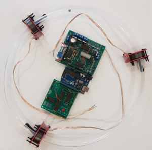
Slowly and carefully flex the main tube back into a circle and position the tube joiner such that it’s evenly positioned over both ends of the tube. Taking extreme care not to kink the tube, push firmly so that the ends cleanly abutt eachother, as in Figure 2. If the joiner is too tight wet a finger under tap water and smear a small amount of water onto the exterior of the main tube. Do not allow water into the tube (it will impede the ball).
Rotate the boards within the tube such that the blue output terminals of the Output board should be somewhere near the EMS with the shorter lead.
Securing your PPA to your baseboard
Gently lift and position the tube with three EMS’s such that the tube is circular and the assembly is in the centre of your base board. Position the clips over the the lower bolt on the inside of the main tube with needle nosed pliers.
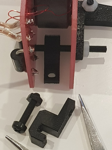
Carefully mark the baseboard through the clip’s hole with the engineering pencil. Now, slide the PPA aside, and drill through the baseboard on the marked spot with a 3mm drill. Reposition the EM’s and tube, and secure the EM with a 12 x M3 nylon screw through the new hole. Screw the nut to the other side. Now, repeat for the other two EM’s with their clips, ensuring that the overall assembly remains circular and centrally positioned.
Optionally, to secure the main circuit boards as well as the electromagnets, you may like to drill holes under
- the four mounting holes (2 on far side of input board, and 2 on far side of output board), and secure those down to your baseboard with the 25mm M3 screws as well.
- the Arduino mounting hole, and secure using the spare M3 screw and nut.
Installing the IRPS
Position an IRPS units on the yoke/connector rod side of each EMS units. Secure each connector rod to its IRPS by fitting the connector rod over the nearby M3 screw protruding from the IRPS underside. It is not necessary to use a nut. For the final IRPS unit, position it on the other side of the EMS closest to the end of the Input Board.
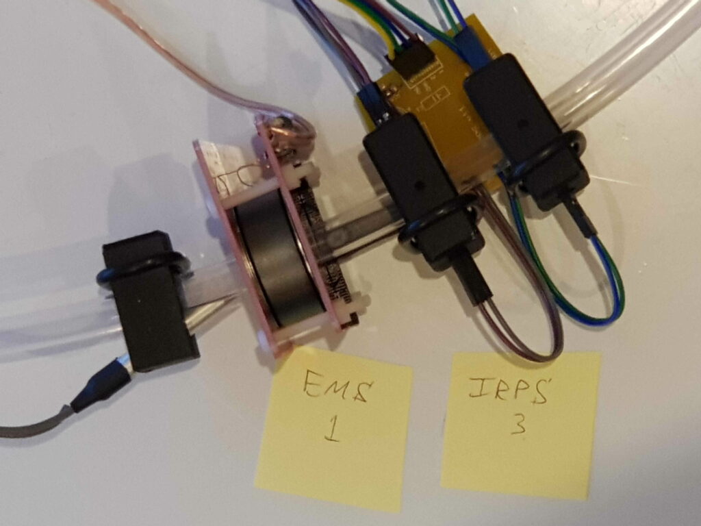
Temporarily label the EMS units and the IRPS units with post-it notes (or similar) as shown in Figure 4, and refer to Table 1. This will assist us setting up the configuration which matches the software.
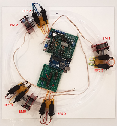
Table 1. The position of each IRPS with its nearest EMS
| IRPS label | EM label | Notes |
| 0 | 0 | IRPS #0 is used for calibration and sits on the exit side of EMS 0. |
| 1 | 0 | IRPS #1 sits on the input side of EMS0 |
| 2 | 2 | |
| 3 | 1 |
Installing the strobes
Position the strobe LEDs into their strobe housings and position after the EMS unit in the direction of travel. The strobe housings are a two part shell, but due to the angle of against the main tube, the top and bottom are mirror symettrical. Unlike the IRPS, the rubber o-ring is assembled on the inside edge of the main tube. See Figure 5. Handle the light tubes carefully as they may be sharp.
The strobes should be placed adjacent to the EMS with the same number according to this list:
P13,P7 – strobe 0
P14,P8 – strobe 1
P15,P9 – strobe 2
P16,P10 – strobe 3 (Super PPA only)
P17,P11 – strobe 4 (Super PPA only)
P18,P12 – strobe 5 (Super PPA only)
For example, the strobe connecting to Output board connections P14 and P8 (strobe 1) should be placed adjacent to EMS 1.
Coffee break ?
You’re doing great. Take a short break so that you don’t make an error when attempting the all important final connections.
Electrical Assembly
Bring your 12V supply cable into the blue terminals on the Output board, carefully noting 12V and Grount polarity
Hook up the four IRPS units to the Input Board sockets with the 4 pin cables. Match up the IRPS number (label) with the Input Board’s label that you made with reference to Table 1. Note the polarity: the wire connecting on the ‘5V’ side of each IRPS must connect to the ‘+’ side of the Input Board. Note that for a Standard size particle accelerator (with 4 IRPS), use the first digit after the X in the Input board label. Eg. the label X0/4 means IRPS 0, the label X1/5 means IRPS 1 etc
Hook up the EM units to the Output Board terminals. Match up the EM number (label) with the Output Board’s label. Note the polarity: the white striped conductor (from the EM terminal closest to the EM board edge) connects to the side of the blue terminals furthest from the power terminal.
Hook up a 4 wire cable between the Output Board’s 4 pin connector labelled ‘Power’ to the 4 pin connector on the Input Board, in the corner nearest the Output Board’s SMPS. Ensure the wire connecting the Output Board ‘+’ label connects to the Input Board’s ‘+’ label.
Hook up a 4 wire cable between the Input Board’s 4 pin connector labelled ‘Out’ (near the centre of the Input Board) to the connector on the Output Board labelled ‘Pump’. The wire connecting the Output Board’s pin closest to the PCB corner must connect to the Input Board’s ‘PWM’ label.
Hook up a 4 wire cable between the Output Board’s 4 pin connector labelled ‘THRCON’ to the Throttle’s only 4 pin connector. The wire connecting the Output Board’s pin closest to the label ‘THRCON’ must connect to the Throttle’s ‘+’ label.
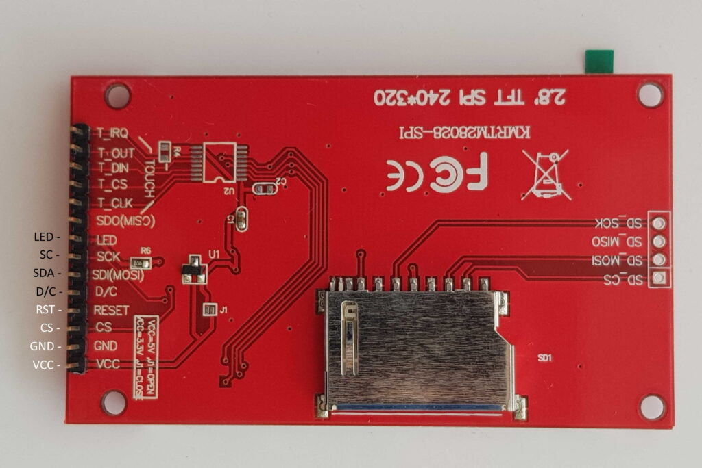
To hook up the TFT screen, connect two four wire jumpers from the input board’s two adjacent connectors labelled SCR1 and SCR2 to the back of the TFT screen. The following picture shows the layout in detail – it’s relatively simple because the 8 screen connections have similar labels on both the PPA Input Board PCB and the back of the TFT, and in the same sequence structured as two blocks of four connections. No other connections to the screen are required.
Congratulations, that was a huge effort. Now you’re just about ready to rock and roll.