There’s no single solution to debugging your particle accelerator, you’ll need to apply knowledge of the design and your debugging experience. Here’s a table to get you started.
| Symptom | Suggested checks |
| Power supplied by no indication of any power reaching the PPA (LEDs, screen) | Check polarity Check voltage level |
| Input Board LED illuminates Screen doesn’t display properly | Check connectors to screen, refer to Input board. Ensure connections between Input Board and Arduino are correct (including polarity). Ensure connections between input and output boards are correct (including polarity) |
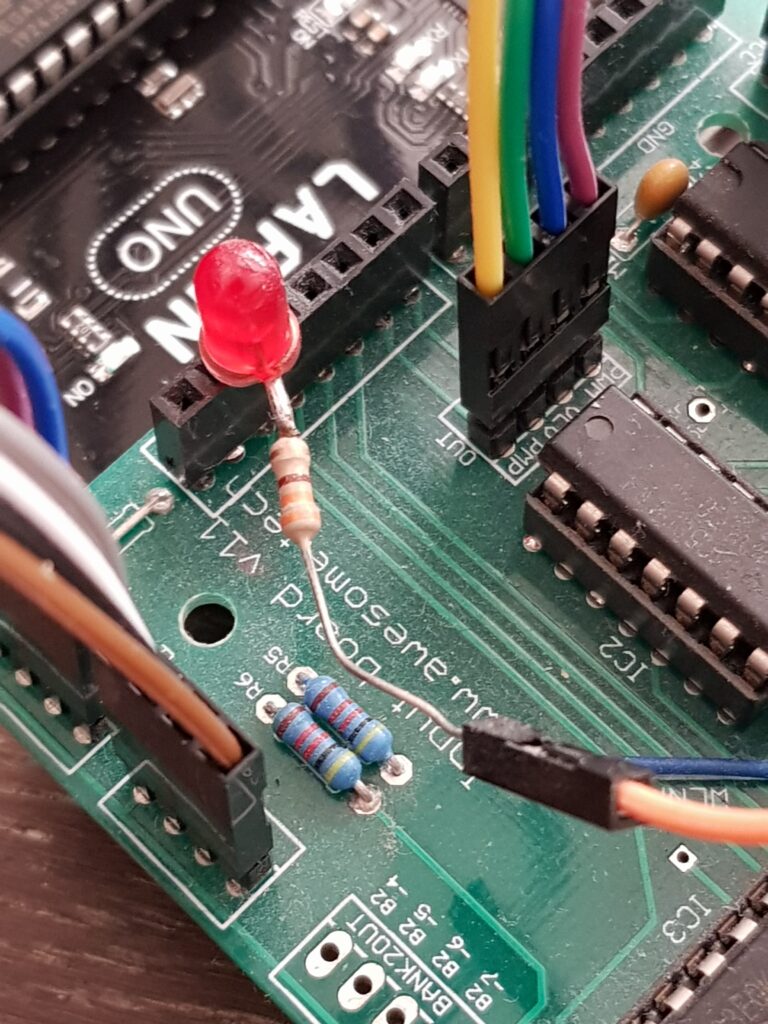
| Power on, screen displays, bar graph and strobes do not operate as ball rotates | IRPS may not be operating correctly – check the IR LED is emitting light by using your mobile phone camera to observe. Check the connections between IRPS and input board (including polarity). Use your oscilloscope or a spare LED with dropper resistor to probe the header sockets on the Input board (see photo below for technique). IRPS signals are not reaching Arduino. Check the Input board pins are correctly engaging with the Arduino. Arduino’s logic is not triggering pulses (should not occur if you use the production code) Check throttle position and screen parameters. |
| Power on, screen displays, bar graph operates but ball does not rotate under power. | Check EMS are enabled (red LED second from the end) Check rotation direction is correct. Check the last red LED on bar graph is OFF. If the LED is on, this indicates that a failsafe condition has occurred. The failsafe occurs when an input pulse is of a length that would cause a magnet to overheat. The production firmware doesn’t cause this condition, so the most likely issue is a construction error on the Output board. If strobes operate, this indicates the pulse signal is likely reaching the EMS, so check the polarity of EMS wiring. In general, check Output board for construction errors. Check throttle position and screen parameters. |