
Let’s be 100% clear, I love my Nomad 883 CNC mill, it got me started with CNC. Now, I’d like to take it further by adding a 4th axis, however this is tricky as the Nomad’s controller, and standard grbl, doesn’t support it. Fortunately, Paul’s developed a brand new ‘Super Gerbil’ 5 axis CNC controller (now on Kickstarter), so I jumped at the chance to use it on the Nomad.
Here’s a preliminary walk through of the process, these instructions will be formalised and expanded upon in due course.
After disconnecting the power, I removed the back panel, which was easy to do, and saw two neatly mounted circuit boards inside a metal frame. The larger board is the x,y,z stepper motor driver, and the smaller board is a dedicated spindle controller.
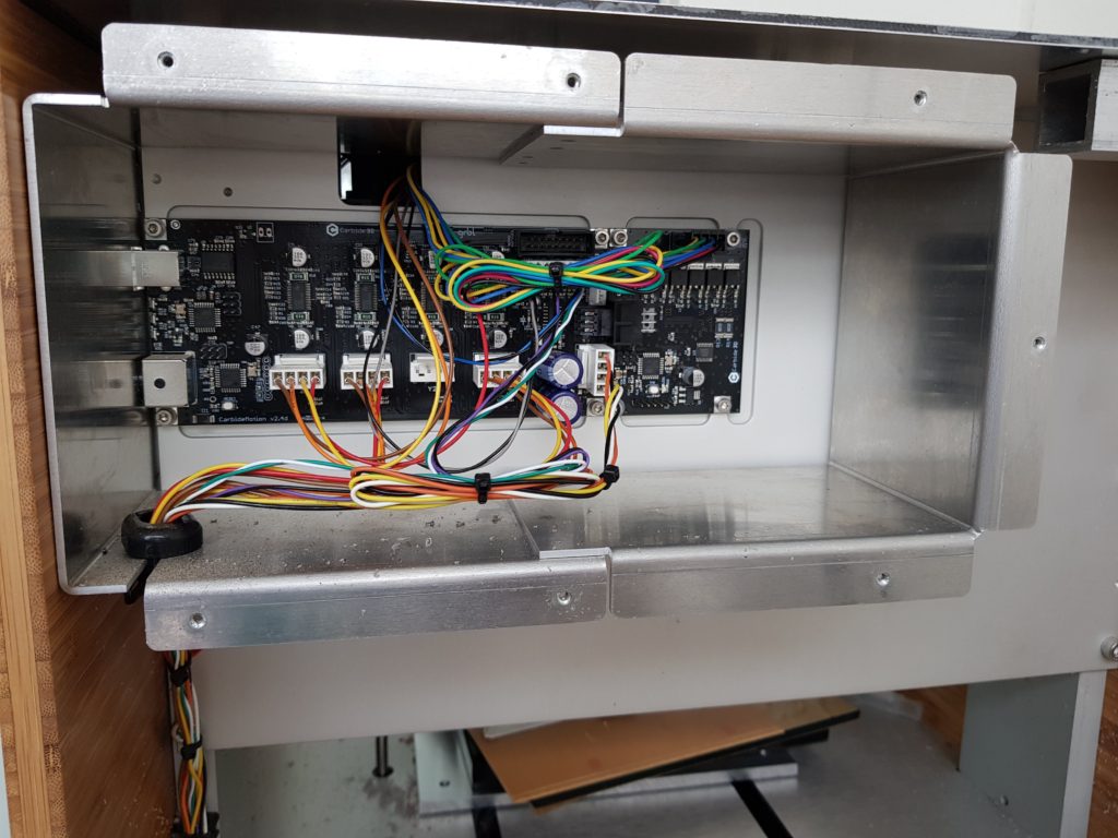
Before doing anything, I labelled all wires coming in/out of the existing controller board, then carefully removed the two boards, which are connected by a 6 pin connector. Keep the two boards in a safe place !
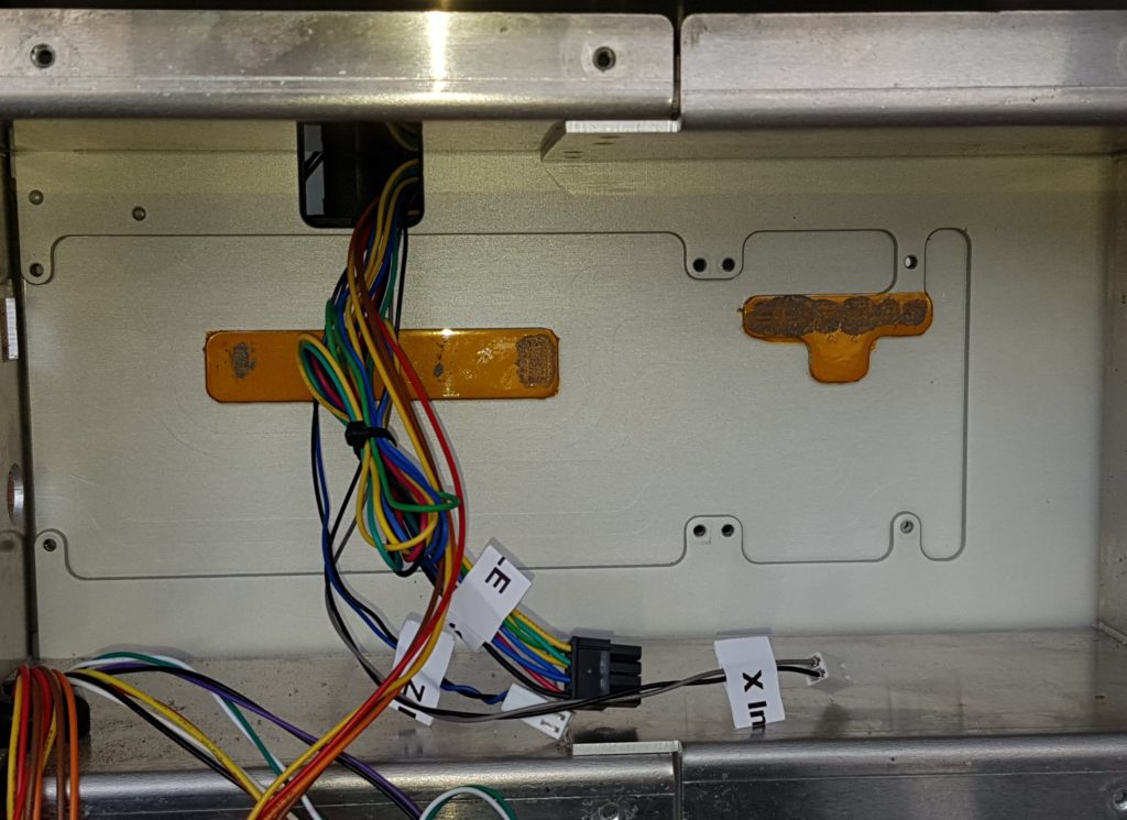
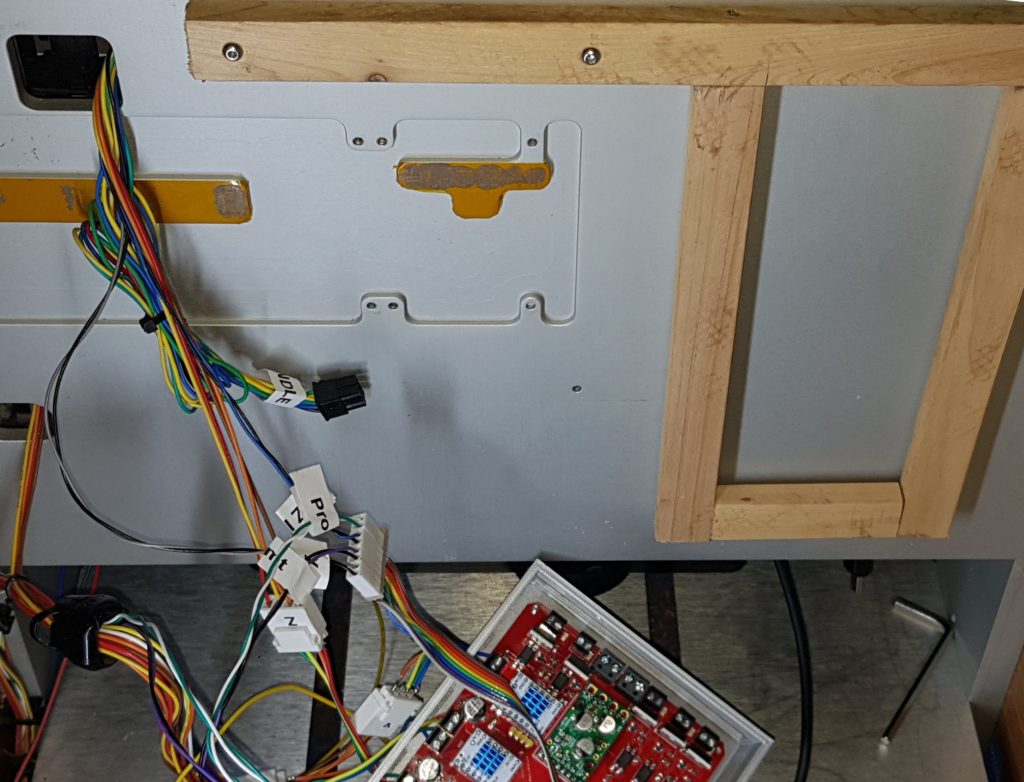
After unscrewing and removing the metal shield, I knocked together a simple wooden frame and attached it to the back panel using the existing holes from the metal shield. Next step was to plug the labelled wires into the respective ports on the Super Gerbil (full instructions will be provided as part of the Super Gerbil Kickstarter). The Super Gerbil uses screw terminals, and the Nomad uses standard Molex connectors. I recommend leaving the existing Nomad connectors as is, and installing short leads with Molex connectors between the Nomad wiring and the Super Gerbil.
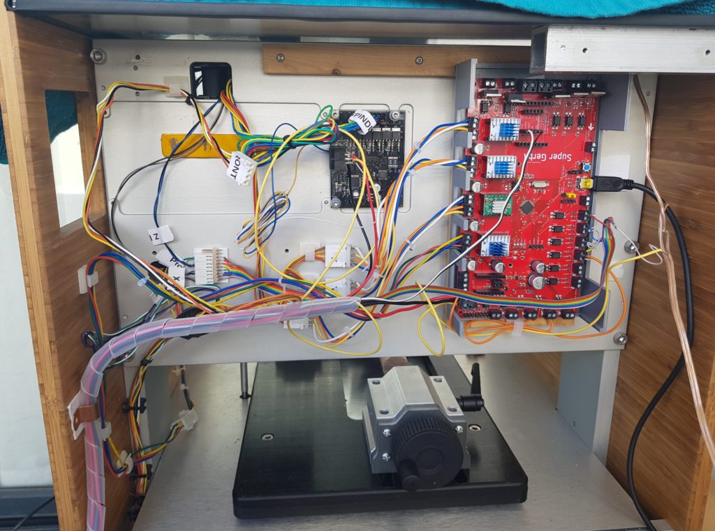
After connecting wires to the ground, 24V and PWM inputs of the Nomad Spindle controller (details to be provided), the next step was to reinstall the Nomad Spindle Controller to its original position and complete the wiring. Final steps were to hang the completed Super Gerbil controller in place then use double sided tape to line up the Molex connectors neatly, and a spiral wrap cable organiser to ensure the cables didn’t fall into the space below. This is important, because as the 4th axis is mounted on the y axis, it could potentially get caught in any wires that hang down. The completed installation looked like this:
Next comes the Super Gerbil Configuration process, which involves loading up recommended gcode control values (to be provided) for the Nomad into the Super Gerbil. The control values specify speed, acceleration, as well as the spatial configuration of the Nomad. Once this process is complete, the Nomad/Super Gerbil should be tested with some existing 3 axis milling jobs.
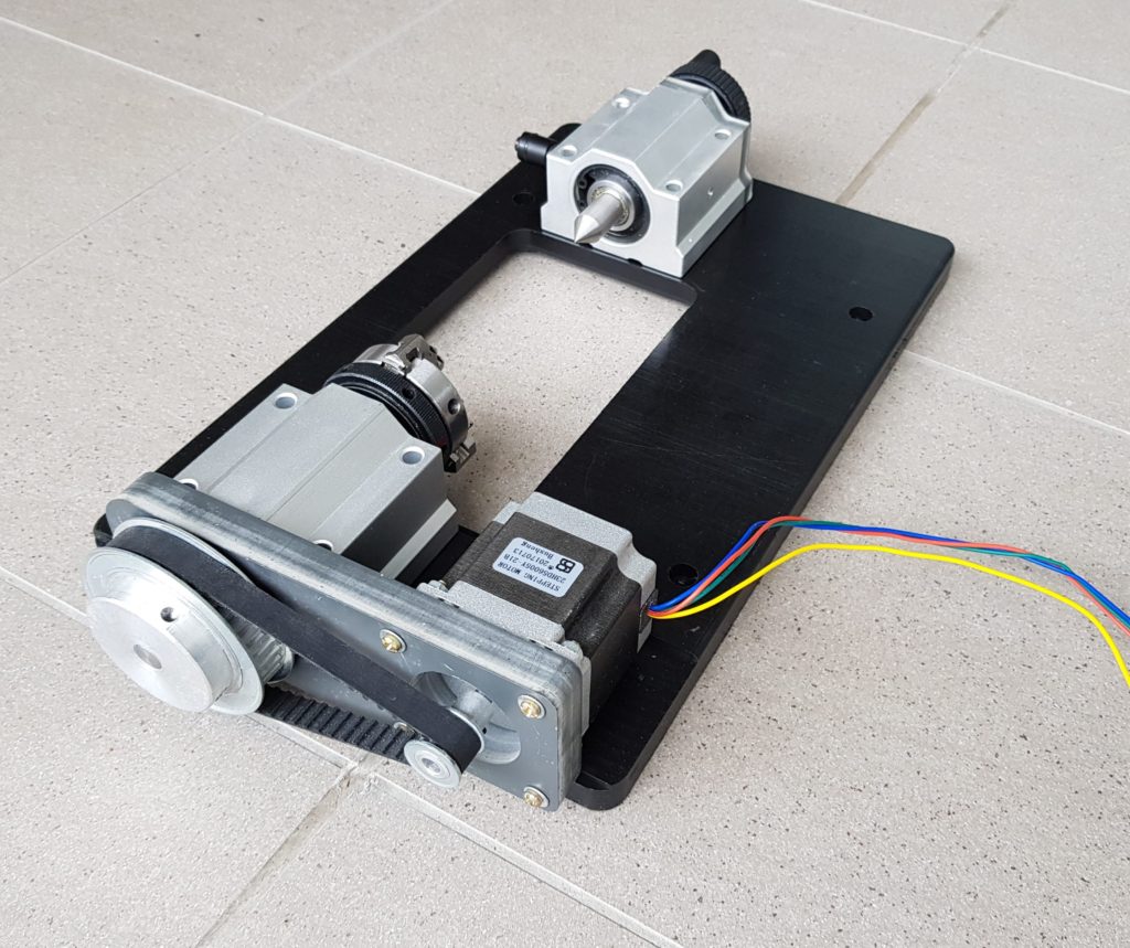
The mechanical installation of the 4th axis is fairly straight forward. The hardware consists of:
- A custom designed baseplate
- Headstock (stepper and chuck)
- Tailstock
- Connecting screws etc
- Electrical connector
First step was to attach the headstock and tailstock to the baseplate with provided nuts and bolts
Next steps were to:
- Install the workpiece between headstock and tailstock prior to mounting the unit on the Nomad. Check for smooth rotation.
- Remove any wasteboard in use on the Nomad, and move the Y-axis towards the front of the unit.
- Screw down the custom baseplate to the Nomad’s aluminium bed with 4 screws.
- Plug in the stepper motor connector to the wires leading to the Super Gerbil. A polarised connector was used to avoid the possibility of reversed connections.
The installed 4th axis now looked like this:
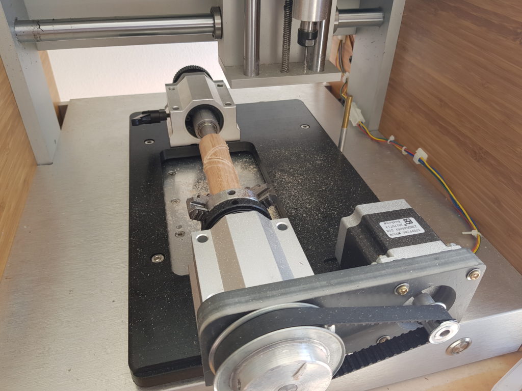
Did you notice I didn’t say replace the back cover of the Nomad ? To maximise the workpiece size that the 4th axis can handle, the tailstock’s motion will actually impinge on the back cover. Given the Nomad’s design as a closed-case desktop mill, it’s a tough call, but I’ll reluctantly cut a small rectangle from the back panel to provide extra clearance for the tail stock. Yes, the movement of the tailstock could be controlled by software alone (or more robustly, an additional limit switch), so that’s an option for people who want to keep the case closed.
At this point, you’re ready to have some fun with your 4th axis ! Keep in mind that a replacement controller isn’t just about hardware, there’s some real work to get the software tool chain right, here’s what we came up with:
A simple example of the CAM simulation job in Fusion360 looks like this:
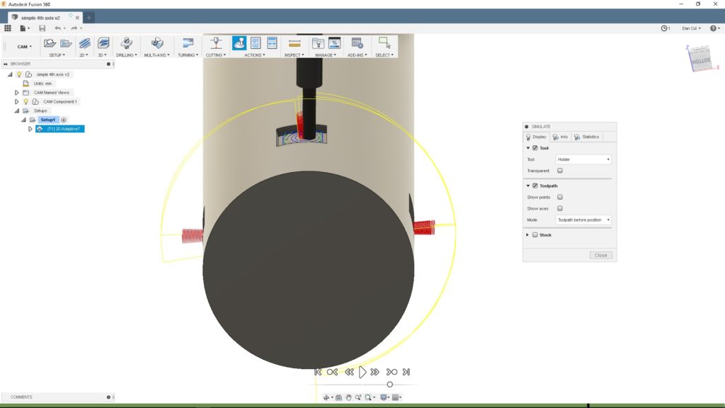
Of course, there’s a learning curve associated with defining simultaneous 4th axis jobs, but NYCNC’s great videos will get you there.
Once your simulation looks good, it’s time to export your gcode. I experimented with a few different Fusion 360 Post Processors, and I’ll probably develop a customised Super Gerbil specific post processor. The Post Processor generates a Gcode file. There’s no need to use Carbide Motion. In fact, I’ve extended Universal Gcode Sender to handle 5 axis grbl gcode, here’s a screenshot of the program ready to run:
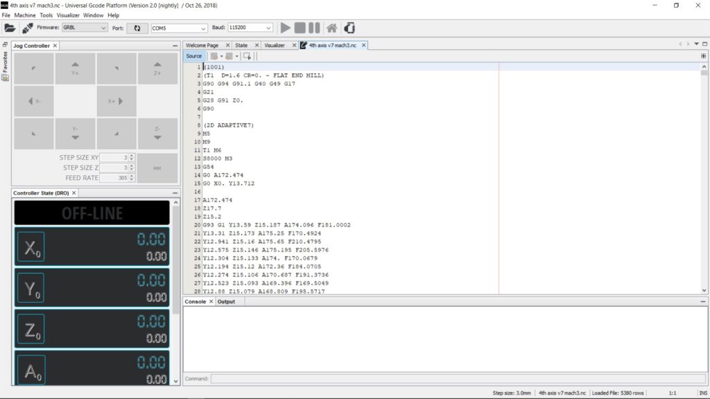
From there, you run the program, the video above shows some 4th axis work in progress