
Setup troubleshooting // hard limits
Quote from Stephanius on December 25, 2017, 8:59 amHello all,
I'm cursed, it seems. ;-] My K40 came with a messed up controller board, which kept running the head into the wall on power up. Now, with the Gerbil installed, I'm trying to get basic homing and head movement working.
When connected using CNCjs 1.9.12, I get Alarm codes 177 and 33 respectively.
I understand that it's a good idea to see the upper left corner as home, since the laser accuracy gets worse the further it is away from it's origin, but I'm confused as to what 0,0 really is now as far as the Gerbil is concerned.
My K40 does not have limit switches, something which I should remedy. Am I right in assuming that I just need to get the right switches, get them in position so that they are closed by the moving head/carriage and connect them to the gerbil controller? I found a wiring diagramm for an Arduino without the Gerbil shield. How do I do that with the shield?
I think that without limit switches, the Gerbil controller cannot automatically find the limits and I would need to manually set the limits, which is fine - except for that I don't know where the head is logically considered to be after it ran into a wall ;-]
Any tips would be greatly appreciated. Merry Christmas! =]
PS: edited title
Hello all,
I'm cursed, it seems. ;-] My K40 came with a messed up controller board, which kept running the head into the wall on power up. Now, with the Gerbil installed, I'm trying to get basic homing and head movement working.
When connected using CNCjs 1.9.12, I get Alarm codes 177 and 33 respectively.
I understand that it's a good idea to see the upper left corner as home, since the laser accuracy gets worse the further it is away from it's origin, but I'm confused as to what 0,0 really is now as far as the Gerbil is concerned.
My K40 does not have limit switches, something which I should remedy. Am I right in assuming that I just need to get the right switches, get them in position so that they are closed by the moving head/carriage and connect them to the gerbil controller? I found a wiring diagramm for an Arduino without the Gerbil shield. How do I do that with the shield?
I think that without limit switches, the Gerbil controller cannot automatically find the limits and I would need to manually set the limits, which is fine - except for that I don't know where the head is logically considered to be after it ran into a wall ;-]
Any tips would be greatly appreciated. Merry Christmas! =]
PS: edited title
Uploaded files: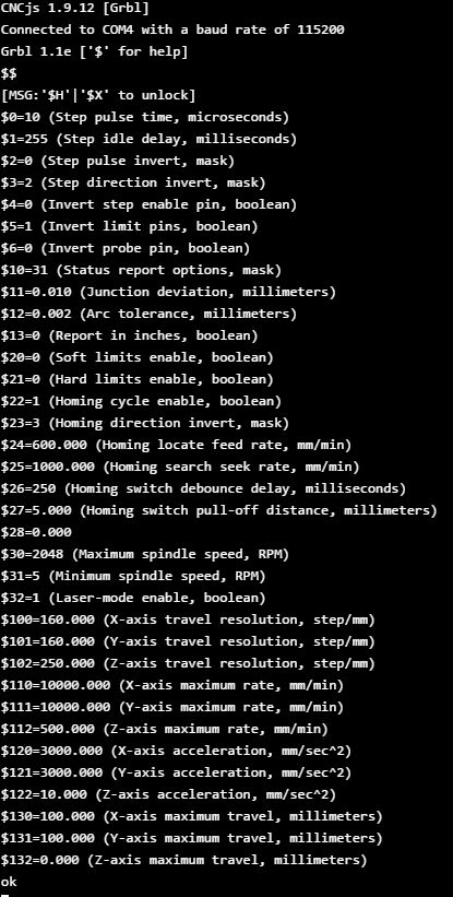
Quote from Stephanius on December 27, 2017, 11:30 amSo, I've done some tinkering. I've slaughtered a game-pad and an old USB mouse to obtain some microswitches. Yay! The mouse also provided a plug that fits on the Gerbil's alternate limit connector, which I'm ashamed to have noticed only after I posted perviously. :-/
I've installed the microswitches as limit switches that engage at the limit of the travel of the X and Y axis, plugged all wires into a breadboard and confirmed that engaging the switches does arrive at the alternate limit connector using my multimeters continuity check.
I also set $21=1 (hard limit on) and $20=0 (soft limit off). Yet, when trying the homing function, the head is still running into the limit, even though the limit switches are engaged.
Any ideas would be much appreciated! =]
So, I've done some tinkering. I've slaughtered a game-pad and an old USB mouse to obtain some microswitches. Yay! The mouse also provided a plug that fits on the Gerbil's alternate limit connector, which I'm ashamed to have noticed only after I posted perviously. :-/
I've installed the microswitches as limit switches that engage at the limit of the travel of the X and Y axis, plugged all wires into a breadboard and confirmed that engaging the switches does arrive at the alternate limit connector using my multimeters continuity check.
I also set $21=1 (hard limit on) and $20=0 (soft limit off). Yet, when trying the homing function, the head is still running into the limit, even though the limit switches are engaged.
Any ideas would be much appreciated! =]
Quote from Chris Luke on December 27, 2017, 7:21 pmAre your limit switches connecting the signal input to GND or to 5V? It should be GND, the input lines are active low and have a weak pull up on them.
You should also make sure the limit switches engage a little before the gantry or head collide with the end of the travel. 1 or 2mm is plenty.
A simple test is to manually engage the limit switches during a homing cycle before the head is anywhere near them, to see if they work. And, since you've been messing with grbl settings, make sure the setting for input polarity matches too ($5 should be 0 iirc).
Are your limit switches connecting the signal input to GND or to 5V? It should be GND, the input lines are active low and have a weak pull up on them.
You should also make sure the limit switches engage a little before the gantry or head collide with the end of the travel. 1 or 2mm is plenty.
A simple test is to manually engage the limit switches during a homing cycle before the head is anywhere near them, to see if they work. And, since you've been messing with grbl settings, make sure the setting for input polarity matches too ($5 should be 0 iirc).
Quote from Stephanius on December 30, 2017, 11:59 amThank you Luke!
Using the Gerbil's alternative limit connector, I had the switches connect the X and Y limit respectively to GND. So that was as you said it should be. Yet, with hard limits enabled and $5=0, I still had the stepper motor run into the wall. I'm guessing I've configured the Gerbil wrong, so it isn't using the hard limits. I see jumpers on the Gerbil, but I am not sure if they are relevant.
Since the switches produced more erratic errors when connected via CNCjs, I looked into the optocoupler solution shown for the generic Arduino/Grbl build:
https://github.com/gnea/grbl/wiki/Wiring-Limit-Switches
I also went ahead and replaced the salvaged switches with switches with levers on them, for more secure engaging and to give myself a bit of room as you suggested.
Given that there is 5V available on the Gerbil's alternative limit switch, I thought that this might work. Obviously, it doesn't, even on the axis where the multimeter reports good results ;-]
My version of the setup looks as shown in the attached picture.
Currently, it should connect the Y-Endstop and X-Endstop to 5V when all is fine, but drop to 0.124V when the limit switches are engaged. Maybe I have this backwards, but if I do, then the limit should be engaged from the second the unit is turned on and it shouldn't move at all.
I have made a mistake in building this circuit, which results in the the Y-Endstop only receiving ~2.7V instead of 5V. Comparing the diagram to my breadboard I fail to find the error. See also: https://youtu.be/cRdDJmwdFRQ
So that leaves me with several questions:
Does the Gerbil work with limits vs 5V or only vs GND?
Does the Gerbil expect 5V on X/Y-Endstop when the switch is engaged or disengaged?
Any idea what I messed up with my limit breadboard?
PS: Where can I hook up my door-safety switch?
Thank you Luke!
Using the Gerbil's alternative limit connector, I had the switches connect the X and Y limit respectively to GND. So that was as you said it should be. Yet, with hard limits enabled and $5=0, I still had the stepper motor run into the wall. I'm guessing I've configured the Gerbil wrong, so it isn't using the hard limits. I see jumpers on the Gerbil, but I am not sure if they are relevant.
Since the switches produced more erratic errors when connected via CNCjs, I looked into the optocoupler solution shown for the generic Arduino/Grbl build:
https://github.com/gnea/grbl/wiki/Wiring-Limit-Switches
I also went ahead and replaced the salvaged switches with switches with levers on them, for more secure engaging and to give myself a bit of room as you suggested.
Given that there is 5V available on the Gerbil's alternative limit switch, I thought that this might work. Obviously, it doesn't, even on the axis where the multimeter reports good results ;-]
My version of the setup looks as shown in the attached picture.
Currently, it should connect the Y-Endstop and X-Endstop to 5V when all is fine, but drop to 0.124V when the limit switches are engaged. Maybe I have this backwards, but if I do, then the limit should be engaged from the second the unit is turned on and it shouldn't move at all.
I have made a mistake in building this circuit, which results in the the Y-Endstop only receiving ~2.7V instead of 5V. Comparing the diagram to my breadboard I fail to find the error. See also: https://youtu.be/cRdDJmwdFRQ
So that leaves me with several questions:
Does the Gerbil work with limits vs 5V or only vs GND?
Does the Gerbil expect 5V on X/Y-Endstop when the switch is engaged or disengaged?
Any idea what I messed up with my limit breadboard?
PS: Where can I hook up my door-safety switch?
Uploaded files: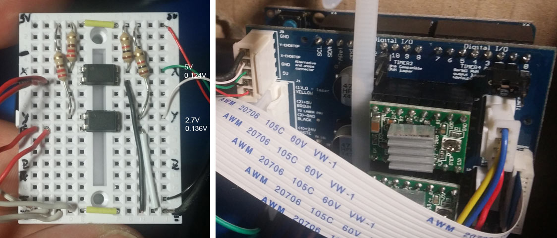
Quote from Paul on December 31, 2017, 1:18 amHi Stephanius, i have send you a pm with some info. Best way to attack this is too troubleshoot one item at a time.
$5 - Limit pins invert, bool
By default, the limit pins are held normally-high with the Arduino's internal pull-up resistor. When a limit pin is low, Grbl interprets this as triggered. For the opposite behavior, just invert the limit pins by typing
$5=1. Disable with$5=0. You may need a power cycle to load the change.NOTE: If you invert your limit pins, you will need an external pull-down resistor wired in to all of the limit pins to prevent overloading the pins with current and frying them.
use $10 to set the reporting on for the limit pins so you know what gerbil sees. Set $10=16.
you can wire the limit switches direct to the external connector on the k40 shield. You don’t need opto couplers.
the safety door can be wired via the laserpower supply, nc switch in the g, p screw terminals. Or you can use the hold feed/resume pins on the k40 shield.
Let me know how it goes, cheers Paul
Hi Stephanius, i have send you a pm with some info. Best way to attack this is too troubleshoot one item at a time.
$5 - Limit pins invert, bool
By default, the limit pins are held normally-high with the Arduino's internal pull-up resistor. When a limit pin is low, Grbl interprets this as triggered. For the opposite behavior, just invert the limit pins by typing $5=1. Disable with $5=0. You may need a power cycle to load the change.
NOTE: If you invert your limit pins, you will need an external pull-down resistor wired in to all of the limit pins to prevent overloading the pins with current and frying them.
use $10 to set the reporting on for the limit pins so you know what gerbil sees. Set $10=16.
you can wire the limit switches direct to the external connector on the k40 shield. You don’t need opto couplers.
the safety door can be wired via the laserpower supply, nc switch in the g, p screw terminals. Or you can use the hold feed/resume pins on the k40 shield.
Let me know how it goes, cheers Paul
Quote from Stephanius on December 31, 2017, 8:17 pmThank you Paul!
I gave your advice a try, but didn't really get anywhere. I'm just too dumb. =/
with $5=0, I connected my switches directly to the Gerbil shield, trying connecting the Endstops vs 5V, and each GND pin on that connector. Then I realized that I wired my switches to be open/disconnected unless pushed, which is exactly the wrong way around.
So I tried with $5=1 and the switches disconnected, just to see if I would once not see MSG: Check limits. That worked, no message. However, the Gerbil still immediately goes into alarm mode, without showing an alarm message.
That might be due to the machine and work position Z Axis showing up as 2147483.648mm, which is ever so slightly outside of the range of my $132, which is currently 0.000.
>> How can I set / how should I set the Z Axis parameters so they quit bugging me?
Now back to the limits, I am happy to rewire my switches to normally closed if that helps, since I understand that not inverting the limit pins is easier.
I understand normally high as carrying the higher of two voltage states to signal a logical 1 vs a logical 0 for the low voltage. The pull up resistor explanation confuses me.
>> If $5=0, am I correct in saying that the X-Axis limit switches should bridge the X-Asis and the 5V pin, unless engaged by the laser head? If not, what should be connected when?
>> Finally, I notice that my laser is briefly engaged when the Gerbil boots. That seems weird to me. Should it do that?
Grbl 1.1e ['$' for help]
[MSG:'$H'|'$X' to unlock]
?<Alarm|MPos:0.000,0.000,2147483.648|Bf:15,127|FS:0,0|WCO:0.000,0.000,0.000>
ok$$
$0=10
$1=25
$2=0
$3=0
$4=0
$5=1
$6=0
$10=31
$11=0.010
$12=0.002
$13=0
$20=0
$21=1
$22=1
$23=0
$24=600.000
$25=1000.000
$26=25
$27=5.000
$28=0.000
$30=2048
$31=5
$32=1
$100=160.000
$101=160.000
$102=0.000
$110=10000.000
$111=10000.000
$112=0.000
$120=3000.000
$121=3000.000
$122=0.000
$130=320.000
$131=230.000
$132=-0.000
ok
Thank you Paul!
I gave your advice a try, but didn't really get anywhere. I'm just too dumb. =/
with $5=0, I connected my switches directly to the Gerbil shield, trying connecting the Endstops vs 5V, and each GND pin on that connector. Then I realized that I wired my switches to be open/disconnected unless pushed, which is exactly the wrong way around.
So I tried with $5=1 and the switches disconnected, just to see if I would once not see MSG: Check limits. That worked, no message. However, the Gerbil still immediately goes into alarm mode, without showing an alarm message.
That might be due to the machine and work position Z Axis showing up as 2147483.648mm, which is ever so slightly outside of the range of my $132, which is currently 0.000.
>> How can I set / how should I set the Z Axis parameters so they quit bugging me?
Now back to the limits, I am happy to rewire my switches to normally closed if that helps, since I understand that not inverting the limit pins is easier.
I understand normally high as carrying the higher of two voltage states to signal a logical 1 vs a logical 0 for the low voltage. The pull up resistor explanation confuses me.
>> If $5=0, am I correct in saying that the X-Axis limit switches should bridge the X-Asis and the 5V pin, unless engaged by the laser head? If not, what should be connected when?
>> Finally, I notice that my laser is briefly engaged when the Gerbil boots. That seems weird to me. Should it do that?
Grbl 1.1e ['$' for help]
[MSG:'$H'|'$X' to unlock]
?
<Alarm|MPos:0.000,0.000,2147483.648|Bf:15,127|FS:0,0|WCO:0.000,0.000,0.000>
ok
$$
$0=10
$1=25
$2=0
$3=0
$4=0
$5=1
$6=0
$10=31
$11=0.010
$12=0.002
$13=0
$20=0
$21=1
$22=1
$23=0
$24=600.000
$25=1000.000
$26=25
$27=5.000
$28=0.000
$30=2048
$31=5
$32=1
$100=160.000
$101=160.000
$102=0.000
$110=10000.000
$111=10000.000
$112=0.000
$120=3000.000
$121=3000.000
$122=0.000
$130=320.000
$131=230.000
$132=-0.000
ok
Quote from Guest on January 2, 2018, 6:35 amHi Stefanus, Gerbil always starts in alarm because it does not know where it is when it is booted up. Unlock the machine via $X and you need to do is to home the machine $H.
now it should be in a known position 0,0 and you can load a gcode. The sequence is build in into the inkscape program. In Cncjs you need to issue a $X, $H.
I’m pretty sure that is the issue. Let me know how you progress.
Hi Stefanus, Gerbil always starts in alarm because it does not know where it is when it is booted up. Unlock the machine via $X and you need to do is to home the machine $H.
now it should be in a known position 0,0 and you can load a gcode. The sequence is build in into the inkscape program. In Cncjs you need to issue a $X, $H.
I’m pretty sure that is the issue. Let me know how you progress.