
Moshi 4.0 Board Install
Quote from glcordon on March 18, 2018, 3:07 pmI've had this K40 for a while now... My connectors are much different than the others. I did my best to map them as they are not color coordinated. I will post pics of where it started and where I mapped them. Let me know if I am correct or if you can provide any assistance.
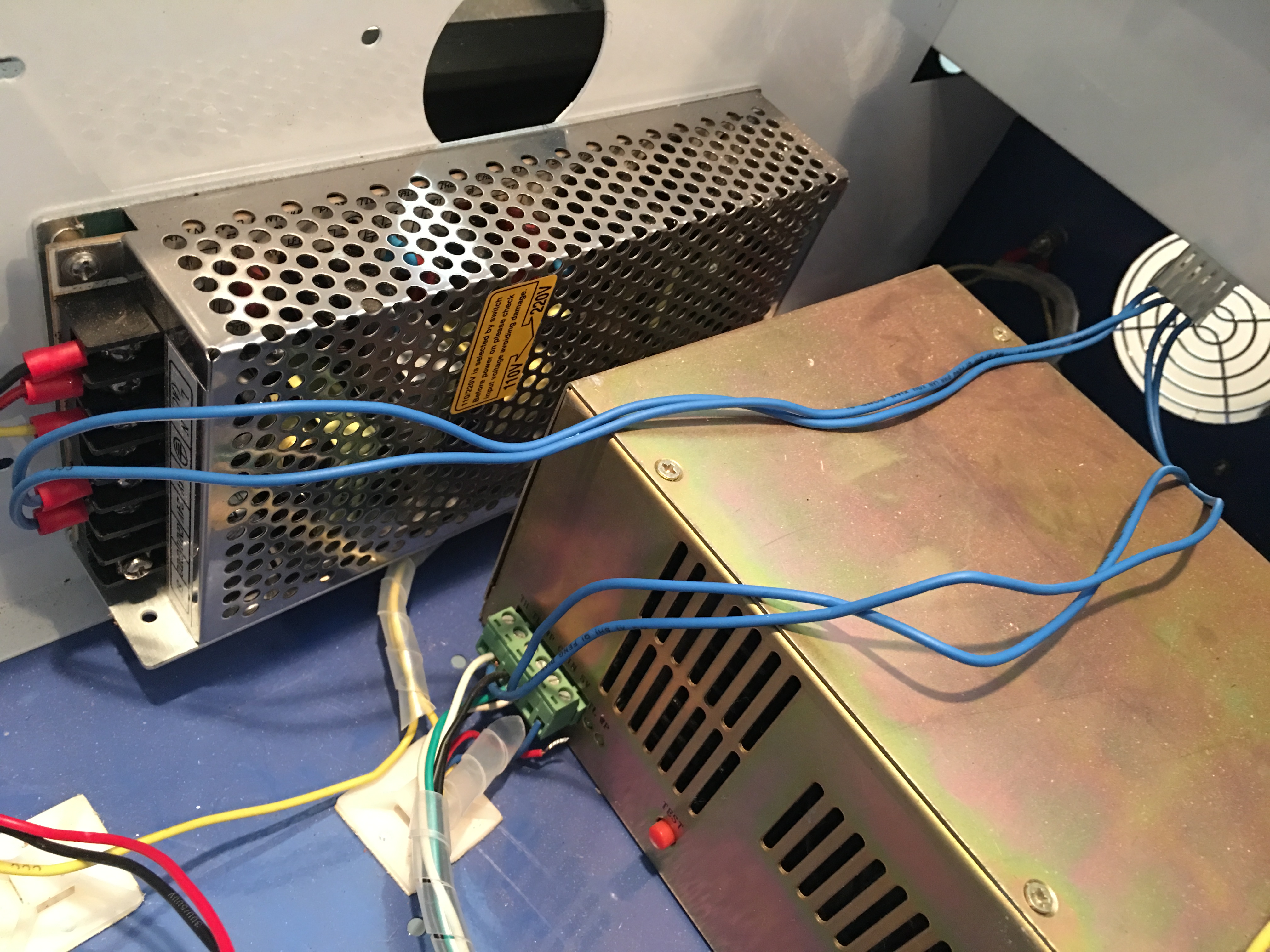
It was a 6 pin config, I cut it down to a 4 pin and reinserted the original wires into it following what was printed on the shield.
Any assistance is appreciated. I am NOT that electrically adept.
Gary
I've had this K40 for a while now... My connectors are much different than the others. I did my best to map them as they are not color coordinated. I will post pics of where it started and where I mapped them. Let me know if I am correct or if you can provide any assistance.
It was a 6 pin config, I cut it down to a 4 pin and reinserted the original wires into it following what was printed on the shield.
Any assistance is appreciated. I am NOT that electrically adept.
Gary
Uploaded files: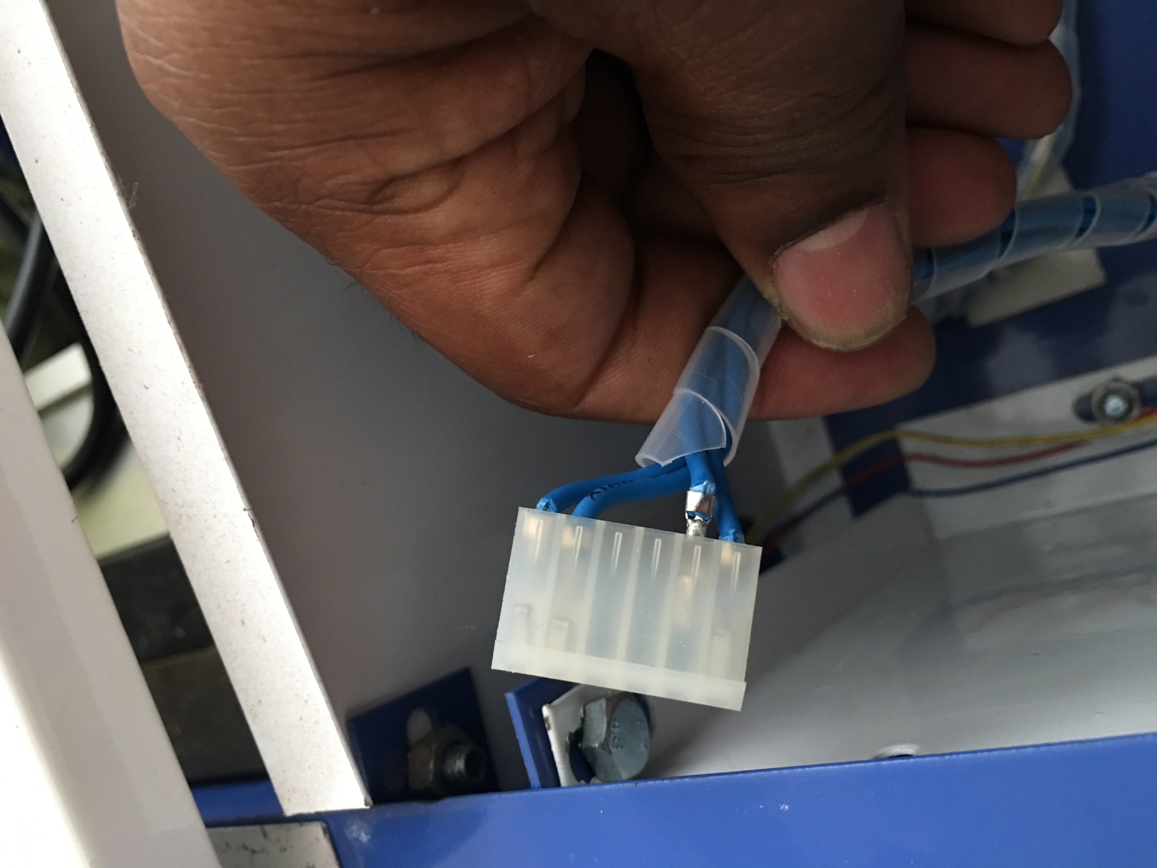
Quote from Paul on March 19, 2018, 1:09 am"(In some older versions of the K40, the connector has 6 positions with 4 wires. You can extract carefully the metal connector inserts and re-seat them in the right positions/sequence in the 6 pin socket connector and slide the 6 pin connector over the 4 male pins. Alternatively you can buy a standard 4 pin (MTA-156 - 4 Position 3.96 mm pitch) PC connector and use this to connect the Gerbil controller to the Laser power supply. See Digikey MTA connectors)"
The power plus sequence is 24v, gnd, 5V, LO (laser on), the current wiring on thge 6 pin connector can be read from the silk screen pcb labels on the stock k40 controller pcb.
Let me know if this works otherwise let me know. Cheers
"(In some older versions of the K40, the connector has 6 positions with 4 wires. You can extract carefully the metal connector inserts and re-seat them in the right positions/sequence in the 6 pin socket connector and slide the 6 pin connector over the 4 male pins. Alternatively you can buy a standard 4 pin (MTA-156 - 4 Position 3.96 mm pitch) PC connector and use this to connect the Gerbil controller to the Laser power supply. See Digikey MTA connectors)"
The power plus sequence is 24v, gnd, 5V, LO (laser on), the current wiring on thge 6 pin connector can be read from the silk screen pcb labels on the stock k40 controller pcb.
Let me know if this works otherwise let me know. Cheers
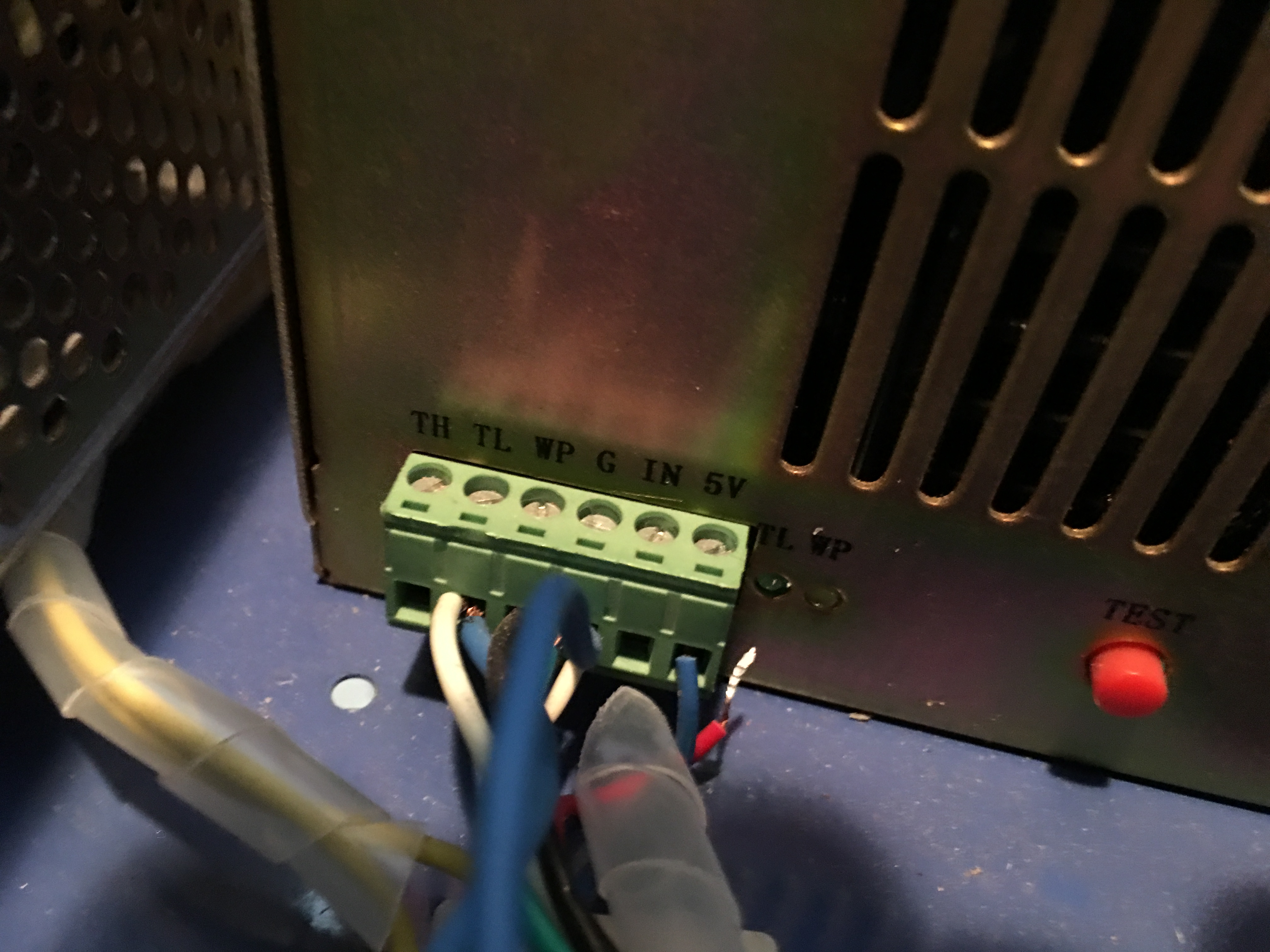
Quote from glcordon on March 20, 2018, 1:07 pmHi Paul, Thanks for that answer... The only problem that I have is that there is nothing labeled Laser On or (LO)... only TH, TL, WP.
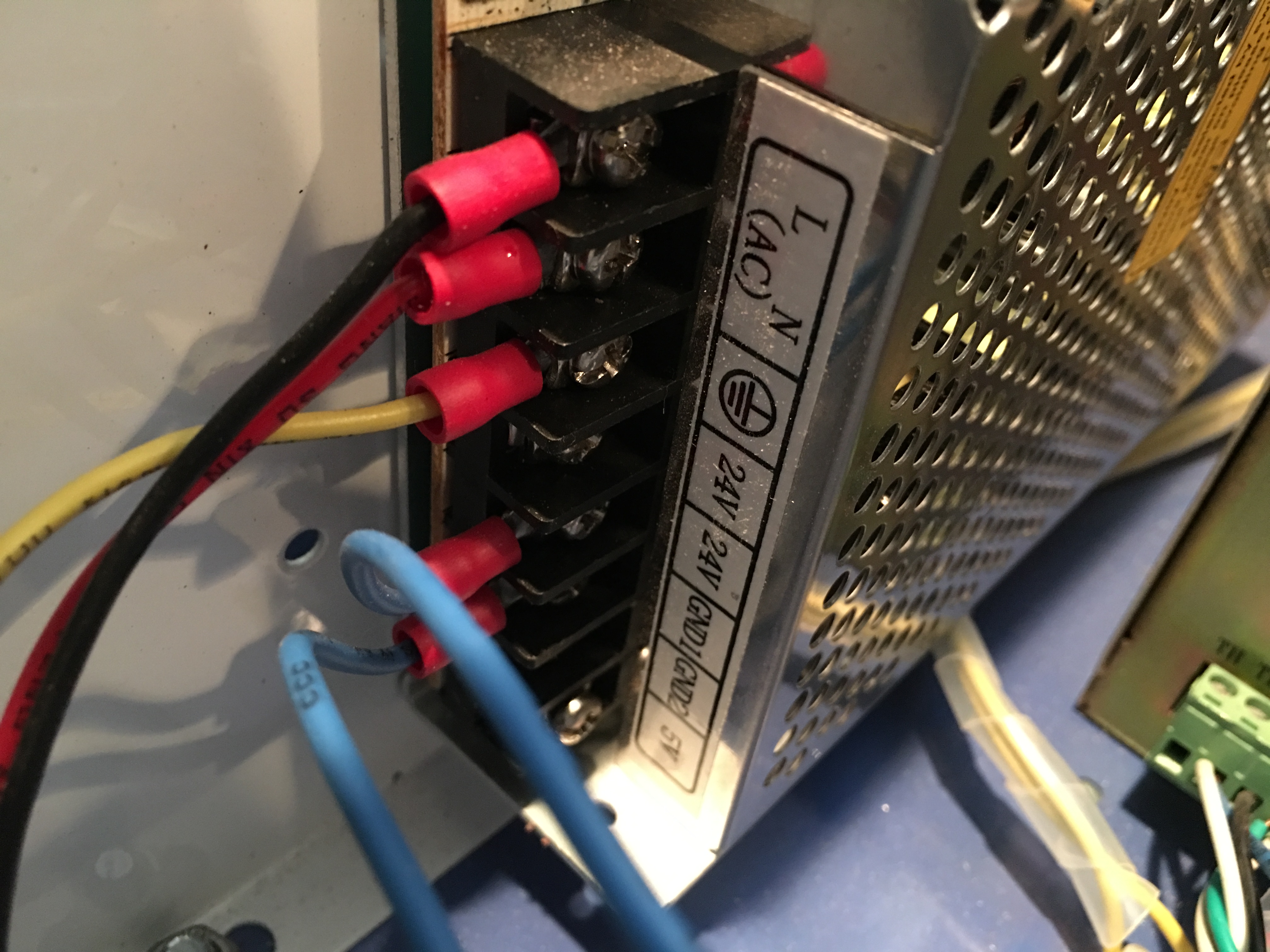
I have the wires set up in the correct order. 24v, gnd, 5v(from the aluminum board), but I dont see a LO for the 4th.
Hi Paul, Thanks for that answer... The only problem that I have is that there is nothing labeled Laser On or (LO)... only TH, TL, WP.
I have the wires set up in the correct order. 24v, gnd, 5v(from the aluminum board), but I dont see a LO for the 4th.
Quote from Paul on March 20, 2018, 6:48 pmOk in that case the laser beam is purely driven by the PWM so it should work fine.
In many cases the LO is an extra protection to ensure that the laser only fires when the operator turns a "on/fire" key or press a radio button. The laser beam is invisible so you cannot see if there is something happening. The WP is water protect so you could add a switch in series with that protection or you could add a three way switch that grounds the pwm input on the laser supply in rest and switches to the gerbil pwm connection when you turn the switch. Both options are just to ensure your safety. You can use your mobile camera to see the laser beam (reflections when wrongly aligned)
Ok in that case the laser beam is purely driven by the PWM so it should work fine.
In many cases the LO is an extra protection to ensure that the laser only fires when the operator turns a "on/fire" key or press a radio button. The laser beam is invisible so you cannot see if there is something happening. The WP is water protect so you could add a switch in series with that protection or you could add a three way switch that grounds the pwm input on the laser supply in rest and switches to the gerbil pwm connection when you turn the switch. Both options are just to ensure your safety. You can use your mobile camera to see the laser beam (reflections when wrongly aligned)
Quote from glcordon on March 21, 2018, 12:36 pmI hate to bother, but... I cannot get the laser to do anything at all... I downloaded CNCJS and it will connect to the Arduino, but it will not move the laser at all.
When I type commands into the window, I get no response. It simply goes to the next line and awaits the next command. Am I doing something wrong?
What would be your rate to do a video conference to walk me through some of these issues?
I hate to bother, but... I cannot get the laser to do anything at all... I downloaded CNCJS and it will connect to the Arduino, but it will not move the laser at all.
When I type commands into the window, I get no response. It simply goes to the next line and awaits the next command. Am I doing something wrong?
What would be your rate to do a video conference to walk me through some of these issues?
Quote from Paul on March 21, 2018, 8:11 pmOk what we need to establish is whether the controller board gets 5V or not. The usb chip is powered by the computer to ensure separation of power supplies (safety). So if the board is powered you should get a status message.
On the processor board is a green power led labeled LED1 on the pcb silkscreen that needs to light up.
Happy to do a teamviewer session if needed, PM me when you're available
Ok what we need to establish is whether the controller board gets 5V or not. The usb chip is powered by the computer to ensure separation of power supplies (safety). So if the board is powered you should get a status message.
On the processor board is a green power led labeled LED1 on the pcb silkscreen that needs to light up.
Happy to do a teamviewer session if needed, PM me when you're available
Quote from glcordon on March 21, 2018, 11:21 pmHi Paul, thanks for your willingness to help. No lights on the board are illuminated at all so that is a power issue. I will PM you in about an hour if you are free...
Hi Paul, thanks for your willingness to help. No lights on the board are illuminated at all so that is a power issue. I will PM you in about an hour if you are free...
Quote from Paul on March 21, 2018, 11:30 pmOk so the board does not get 5V, let's check whether your power supply provides 5v otherwise you need to supply power separately to the board. Options are 5v directly to the power plug on the shield or 9V dc to the jack barrel plug on the processor board (it has its voltage regulator to create 5v from the supplied 9v)
Ok so the board does not get 5V, let's check whether your power supply provides 5v otherwise you need to supply power separately to the board. Options are 5v directly to the power plug on the shield or 9V dc to the jack barrel plug on the processor board (it has its voltage regulator to create 5v from the supplied 9v)
Quote from glcordon on March 22, 2018, 12:14 amDoes the amperage matter on the 9v or 12v barrel adapter? I also PMd you LinkedIn
Does the amperage matter on the 9v or 12v barrel adapter? I also PMd you LinkedIn
Quote from Paul on March 22, 2018, 12:20 amNo it doesn't matter. The board takes very little current. 100mA should be more than sufficient.
No it doesn't matter. The board takes very little current. 100mA should be more than sufficient.
Quote from glcordon on March 22, 2018, 4:47 pmHi Paul...
I bought an external power supply to power the device. Now I am getting an alarm
<Alarm|MPos:-480.000,-480.000,0.000|Bf:15,127|FS:0,0|Pn:XZ|WCO:0.000,0.000,0.000>
ok
>
Also there is a flashing red and orange light on the board... What is happening?
Gary
Hi Paul...
I bought an external power supply to power the device. Now I am getting an alarm
<Alarm|MPos:-480.000,-480.000,0.000|Bf:15,127|FS:0,0|Pn:XZ|WCO:0.000,0.000,0.000>
ok
>
Also there is a flashing red and orange light on the board... What is happening?
Gary
Uploaded files: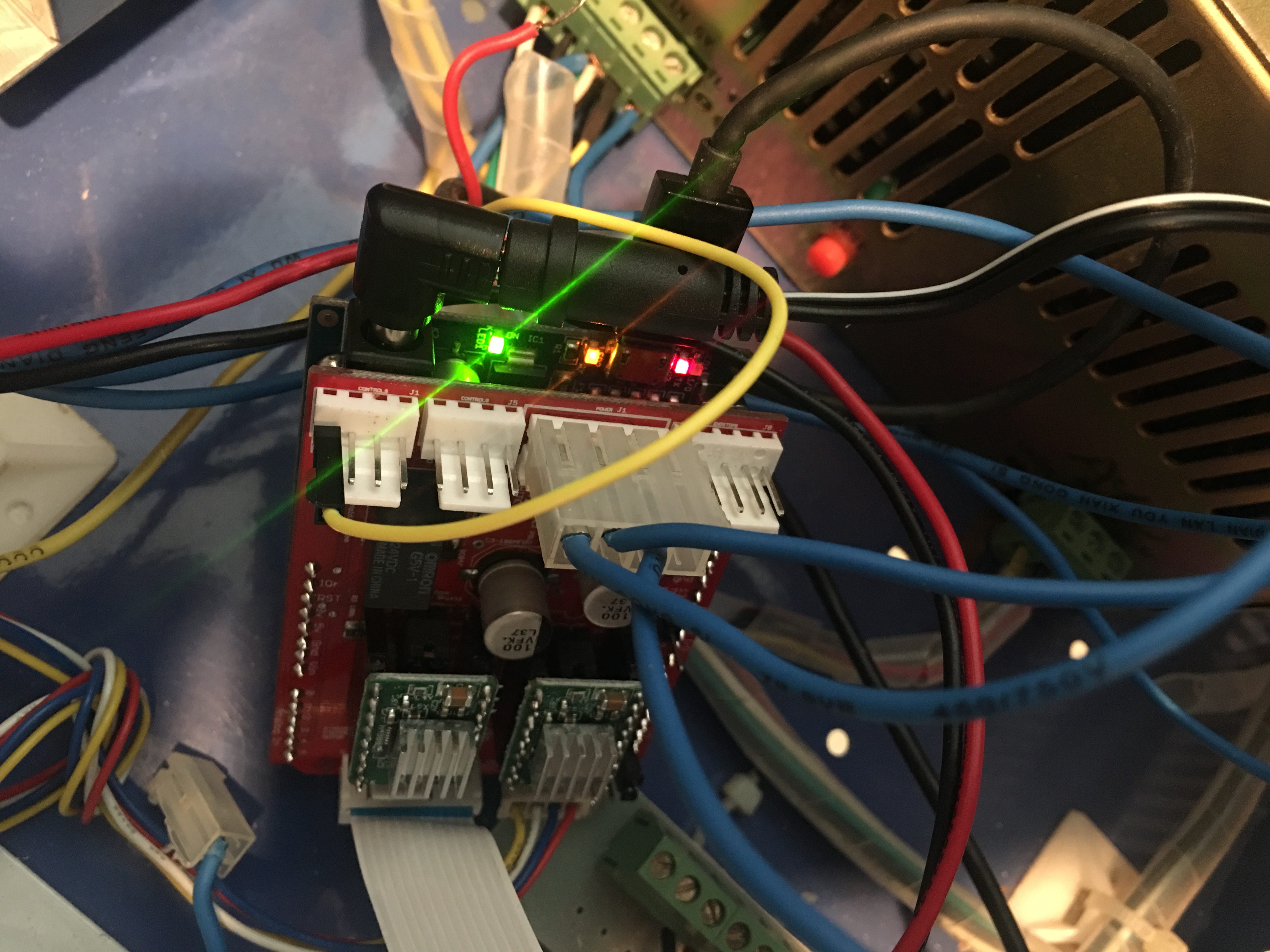
Quote from glcordon on March 22, 2018, 5:29 pmDisregard... I got it to work... Now it just won't fire the laser unless I hold the test switch as it is going through the process...
Disregard... I got it to work... Now it just won't fire the laser unless I hold the test switch as it is going through the process...
Quote from Paul on March 22, 2018, 5:55 pmGood to hear that you got the board working. You can use the LO switch output from the gerbil shield to switch tge test button. Just follow the switch leads and see where they connect on the laser power supply. One of those connections can be used. Measure the voltage on them and let me know so I can advise you.
Good to hear that you got the board working. You can use the LO switch output from the gerbil shield to switch tge test button. Just follow the switch leads and see where they connect on the laser power supply. One of those connections can be used. Measure the voltage on them and let me know so I can advise you.
Quote from glcordon on March 22, 2018, 8:17 pmPaul... This thing is bonkers... Now it will not connect to my computer at all. My computer does not recognize the board anymore... When I reconnected it and typed $H, it started going the opposite direction... I hurried and turned it off, and now it will not reconnect.
Any help is appreciated!
Paul... This thing is bonkers... Now it will not connect to my computer at all. My computer does not recognize the board anymore... When I reconnected it and typed $H, it started going the opposite direction... I hurried and turned it off, and now it will not reconnect.
Any help is appreciated!
Quote from Paul on March 22, 2018, 9:46 pmIf the machine homes into the opposite direction then turn the Y axis connector 180 degrees (alternative is to use configuration "$3=2").
If the USB is not recognised: either reboot, power on/off or install the FTDI drivers. Ensure you have the latest Windows updates. Old versions of windows has generic issues with usb drivers because they did not consider the IoT users. The FTDI drivers can be downloaded from the FTDI site (for the link, see download menu on this site).
Send me an email at pauljacobdegroot at gmail so I can give you a bit more support.
If the machine homes into the opposite direction then turn the Y axis connector 180 degrees (alternative is to use configuration "$3=2").
If the USB is not recognised: either reboot, power on/off or install the FTDI drivers. Ensure you have the latest Windows updates. Old versions of windows has generic issues with usb drivers because they did not consider the IoT users. The FTDI drivers can be downloaded from the FTDI site (for the link, see download menu on this site).
Send me an email at pauljacobdegroot at gmail so I can give you a bit more support.